Aggregation load sharing configuration example, Network requirements, Configuration procedure – H3C Technologies H3C S7500E Series Switches User Manual
Page 147
11-23
-------------------------------------------------------------------------------
BAGG1 D 0x8000, 000f-e2ff-0002 3 0 Shar
The output shows that link aggregation group 1 is a load sharing Layer 2 dynamic aggregation group
and it contains three selected ports.
# Display the global link-aggregation load sharing criteria on Device A.
[DeviceA] display link-aggregation load-sharing mode
Link-Aggregation Load-Sharing Mode:
destination-mac address, source-mac address
The output shows that all link aggregation groups created on the device perform load sharing based on
source and destination MAC addresses.
Aggregation Load Sharing Configuration Example
Network requirements
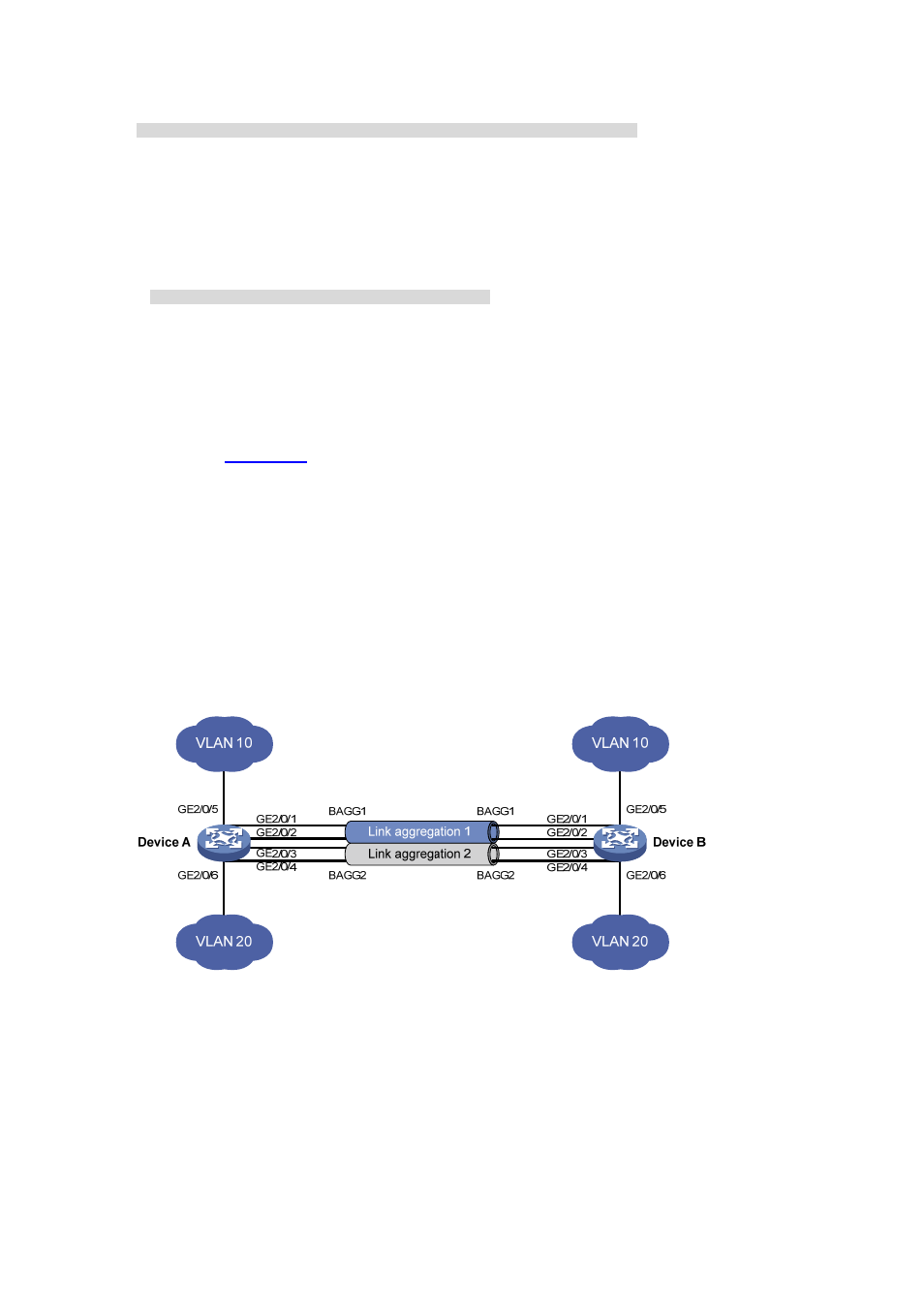
As shown in
Device A and Device B are connected by their Layer 2 Ethernet interfaces GigabitEthernet 2/0/1
through GigabitEthernet 2/0/4.
Configure two Layer 2 static link aggregation groups (1 and 2) on Device A and Device B
respectively, enable VLAN 10 at one end of the aggregate link to communicate with VLAN 10 at
the other end, and VLAN 20 at one end to communicate with VLAN 20 at the other end..
Configure the load sharing criterion for link aggregation group 1 as the source MAC addresses of
packets and the load sharing criterion for link aggregation group 2 as the destination MAC
addresses of packets to enable traffic to be load-shared across aggregation group member ports.
Figure 11-8
Network diagram for aggregation load sharing configuration
Configuration procedure
1) Configure
Device
A
# Create VLAN 10, and assign port GigabitEthernet 2/0/5 to VLAN 10
<DeviceA> system-view
[DeviceA] vlan 10
[DeviceA-vlan10] port gigabitEthernet 2/0/5
[DeviceA-vlan10] quit
# Create VLAN 20, and assign port GigabitEthernet 2/0/6 to VLAN 20.