Configuration procedure – H3C Technologies H3C S7500E Series Switches User Manual
Page 303
21-20
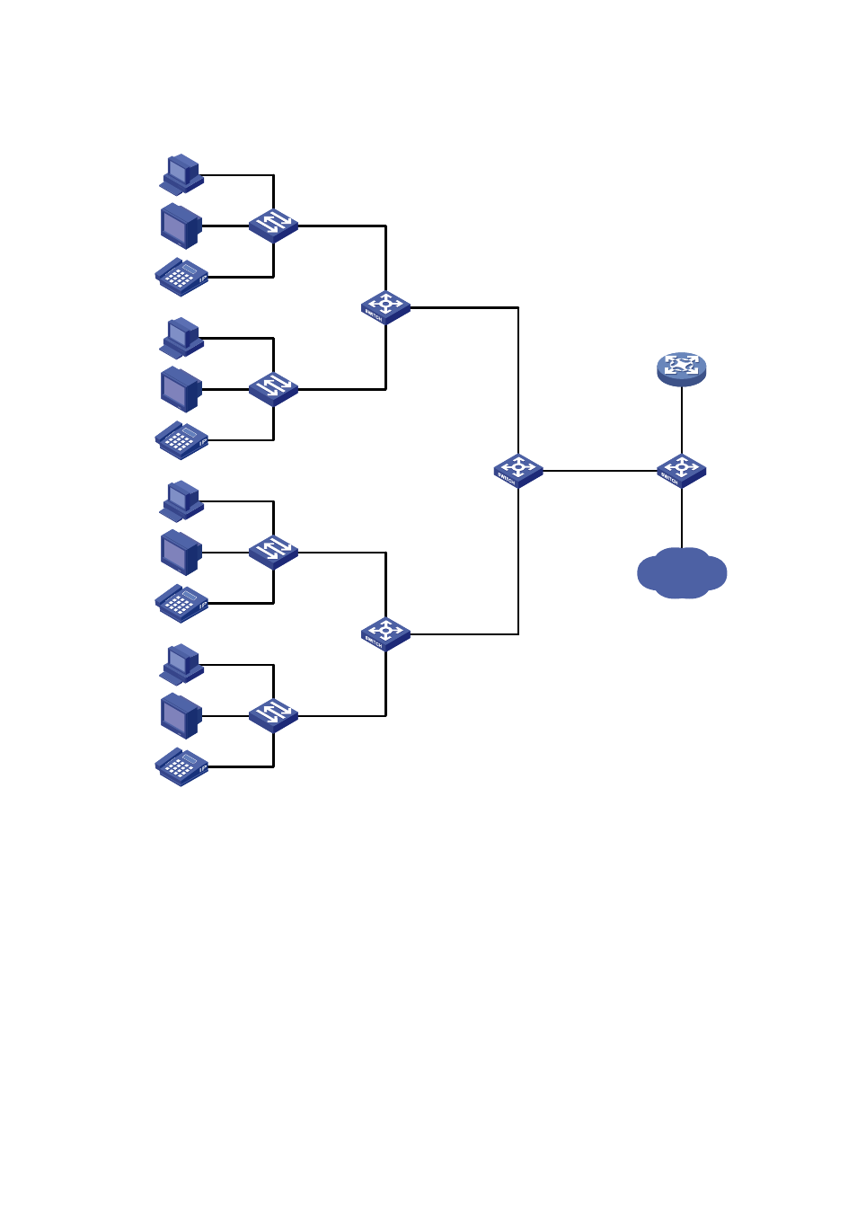
Figure 21-8
Network diagram for one-to-one and many-to-one VLAN mapping configuration
VLAN 103 - 104 -> VLAN 501
VLAN 203 - 204 -> VLAN 502
VLAN 303 - 304 -> VLAN 503
Campus switch
Switch C
Distribution
network
DHCP client
DHCP server
Wiring-closet
Switch A
VLAN 1 -> VLAN 101
VLAN 2 -> VLAN 201
VLAN 3 -> VLAN 301
VLAN 1 -> VLAN 102
VLAN 2 -> VLAN 202
VLAN 3 -> VLAN 302
PC
VoD
VoIP
VLAN 2
Home gateway
VLAN 1
VLAN 3
PC
VoD
VoIP
VLAN 2
Home gateway
VLAN 1
VLAN 3
VLAN 1 -> VLAN 103
VLAN 2 -> VLAN 203
VLAN 3 -> VLAN 303
VLAN 1 -> VLAN 104
VLAN 2 -> VLAN 204
VLAN 3 -> VLAN 304
PC
VoD
VoIP
VLAN 2
Home gateway
VLAN 1
VLAN 3
PC
VoD
VoIP
VLAN 2
Home gateway
VLAN 1
VLAN 3
Wiring-closet
Switch B
GE2/0/1
GE2/0/2
GE2/0/1
GE2/0/2
GE2/0/1
GE2/0/2
GE2/0/3
GE2/0/3
GE2/0/3
GE2/0/1
Switch D
VLAN 101 - 102 -> VLAN 501
VLAN 201 - 202 -> VLAN 502
VLAN 301 - 302 -> VLAN 503
Configuration procedure
1) Configuring Switch A
# Create the CVLANs and the SVLANs.
<SwitchA> system-view
[SwitchA] vlan 2 to 3
[SwitchA] vlan 101 to 102
[SwitchA] vlan 201 to 202
[SwitchA] vlan 301 to 302
# Configure uplink policies p1 and p2 to enable one SVLAN to transmit one service for one customer.
[SwitchA] traffic classifier c1
[SwitchA-classifier-c1] if-match customer-vlan-id 1
[SwitchA-classifier-c1] traffic classifier c2
[SwitchA-classifier-c2] if-match customer-vlan-id 2