Vlan mapping implementations, One-to-one vlan mapping, Figure 21-3 – H3C Technologies H3C S7500E Series Switches User Manual
Page 287
21-4
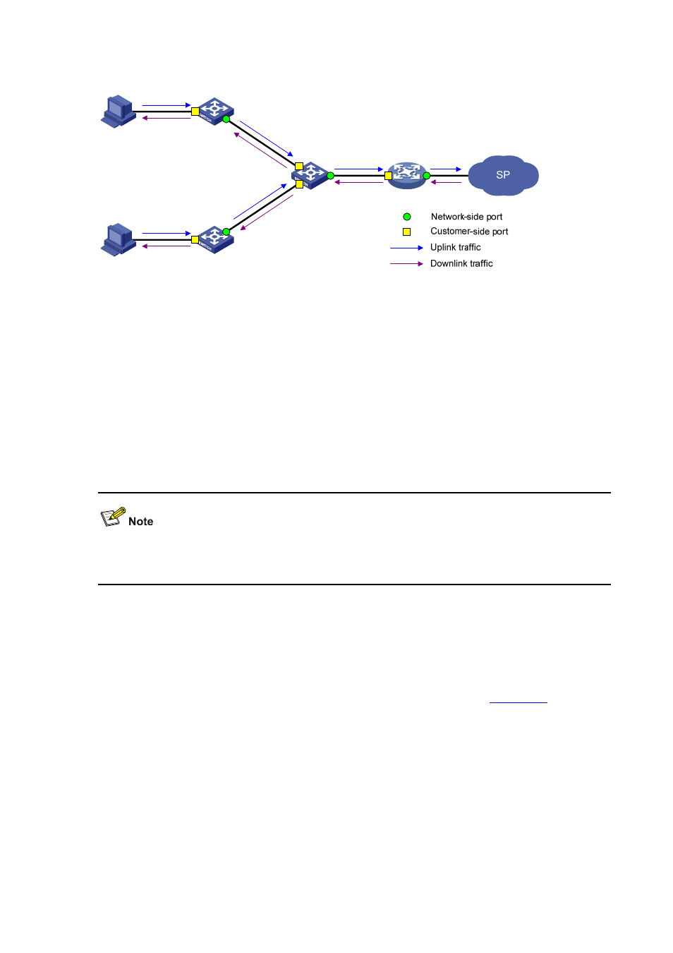
Figure 21-3
Basic concepts of VLAN mapping
Uplink traffic: Traffic transmitted from the customer network to the service provider network.
Downlink traffic: Traffic transmitted from the service provider network to the customer network.
Network-side port: A port connected to the service provider network.
Customer-side port: A port connected to the customer network.
Uplink policy: A QoS policy that defines VLAN mapping rules for uplink traffic.
Downlink policy: A QoS policy that defines VLAN mapping rules for downlink traffic.
Customer VLANs (CVLANs): VLANs assigned for customers.
Service provider VLANs (SVLANs): VLANs assigned for transmitting traffic across the service
provider network.
For more information about QoS policies, see QoS Configuration Approaches in the ACL and QoS
Configuration Guide
.
VLAN Mapping Implementations
This section describes how VLAN mapping is implemented on your device.
One-to-one VLAN mapping
Implement one-to-one VLAN mapping on the customer-side port, as shown in
:
Apply an uplink policy to the incoming traffic, mapping each CVLAN ID to a unique SVLAN ID.
When a packet arrives, the switch replaces its CVLAN ID with the matching SVLAN ID.
Apply a downlink policy to the outgoing traffic, mapping each SVLAN ID back to its corresponding
CVLAN ID. When forwarding a packet out of the port, the switch replaces its SVLAN ID with the
matching CVLAN ID.