Displaying and maintaining isolate-user-vlan, Isolate-user-vlan configuration example, Network requirements – H3C Technologies H3C S7500E Series Switches User Manual
Page 244: Configuration procedure, 3 isolate-user-vlan configuration example
17-3
After associating an isolate-user-VLAN with the specified secondary VLANs, you cannot add/remove a
access port to/from each involved VLAN or remove each involved VLAN. To do that, you must cancel
the association first.
Displaying and Maintaining Isolate-User-VLAN
To do...
Use the command...
Remarks
Display the mapping between an
isolate-user-VLAN and its secondary VLAN(s)
display isolate-user-vlan
[ isolate-user-vlan-id ]
Available in any view
Isolate-User-VLAN Configuration Example
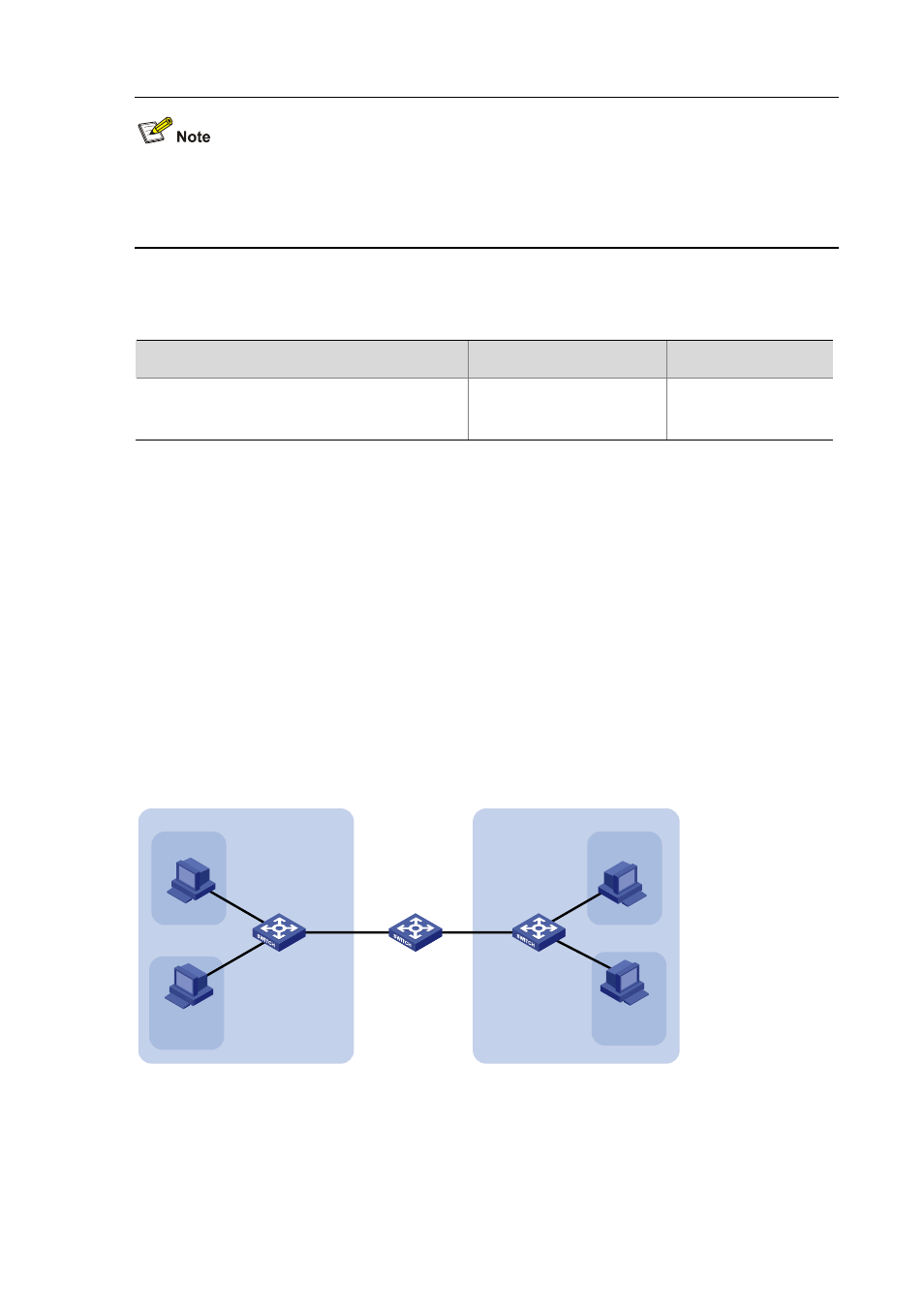
Network requirements
Connect Device A to downstream devices Device B and Device C;
Configure VLAN 5 on Device B as an isolate-user-VLAN, assign the uplink port GigabitEthernet
2/0/5 to VLAN 5, and associate VLAN 5 with secondary VLANs VLAN 2 and VLAN 3. Assign
GigabitEthernet 2/0/2 to VLAN 2 and GigabitEthernet 2/0/1 to VLAN 3.
Configure VLAN 6 on Device C as an isolate-user-VLAN, assign the uplink port GigabitEthernet
2/0/5 to VLAN 6, and associate VLAN 6 with secondary VLANs VLAN 3 and VLAN 4. Assign
GigabitEthernet 2/0/3 to VLAN 3 and GigabitEthernet 2/0/4 to VLAN 4.
For Device A, Device B only has VLAN 5 and Device C only has VLAN 6.
Figure 17-2
Network diagram for isolate-user-VLAN configuration
GE2
/0/1
GE
2/0
/2
VLAN 5
GE
2/0
/3
GE2
/0/4
VLAN 6
GE2/0/5
GE2/0/5
Device A
Device B
Device C
Host A
Host B
Host C
Host D
VLAN 3
VLAN 2
VLAN 3
VLAN 4
Configuration procedure
The following part provides only the configuration on Device B and Device C.
1) Configure
Device
B
# Configure the isolate-user-VLAN.