Displaying and maintaining super vlan, Super vlan configuration example, Network requirements – H3C Technologies H3C S7500E Series Switches User Manual
Page 239: 3 super vlan configuration example
16-3
The VLAN interface IP address in the above table is the IP address of the associated super VLAN.
For more information about the local-proxy-arp enable command and the local proxy ARP function,
refer to ARP Configuration in the Layer 3 - IP Services Configuration Guide.
You cannot configure a super VLAN as the guest VLAN for a port, and vice versa. For more
information about guest VLAN, refer to 802.1X Configuration in the Security Configuration Guide.
You can configure Layer 2 multicast for a super VLAN. However, the configuration cannot take
effect.
You can configure DHCP, Layer 3 multicast, dynamic routing, and NAT for the VLAN interface of a
super VLAN. However, only DHCP can take effect.
Configuring VRRP for the VLAN interface of a super VLAN affects network performance.
Therefore, you are recommended not to configure this function in normal cases.
Displaying and Maintaining Super VLAN
To do…
Use the command…
Remarks
Display the mapping between a super
VLAN and its sub-VLAN(s)
display supervlan
[ supervlan-id ]
Available in any view
Super VLAN Configuration Example
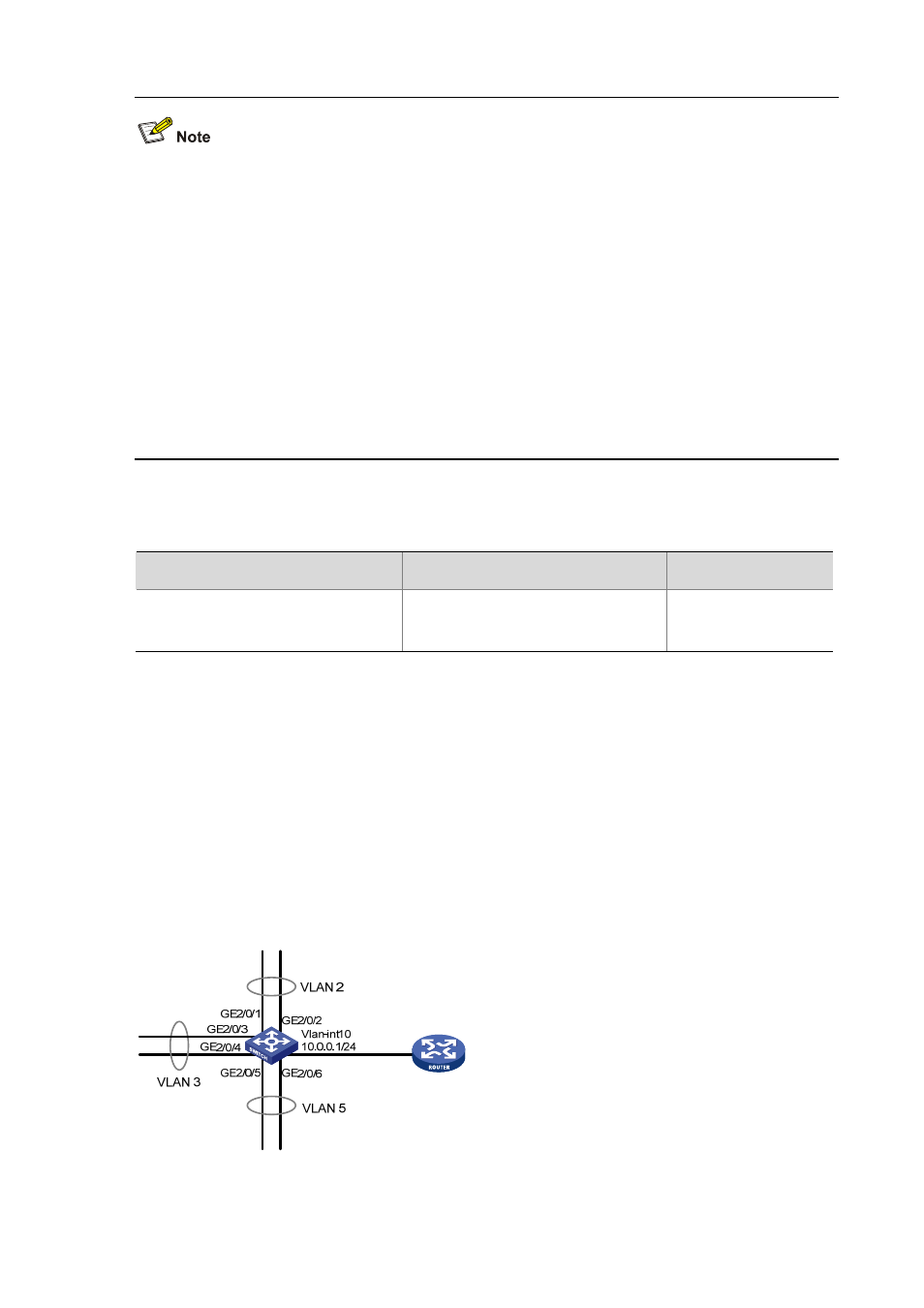
Network requirements
Create super VLAN 10, and configure its VLAN interface IP address as 10.0.0.1/24.
Create the sub-VLANs VLAN 2, VLAN 3, and VLAN 5.
Assign GigabitEthernet 2/0/1 and GigabitEthernet 2/0/2 to VLAN 2, GigabitEthernet 2/0/3 and
GigabitEthernet 2/0/4 to VLAN 3, and GigabitEthernet 2/0/5 and GigabitEthernet 2/0/6 to VLAN 5.
The sub-VLANs are isolated at Layer 2 but connected at Layer 3.
Figure 16-1
Network diagram for super-VLAN configuration