Basic concepts in mstp, Mst region – H3C Technologies H3C S7500E Series Switches User Manual
Page 163
13-11
MSTP features the following:
MSTP supports mapping VLANs to spanning tree instances by means of a VLAN-to-instance
mapping table. MSTP can reduce communication overheads and resource usage by mapping
multiple VLANs to one instance.
MSTP divides a switched network into multiple regions, each containing multiple spanning trees
that are independent of one another.
MSTP prunes a loop network into a loop-free tree, thus avoiding proliferation and endless cycling
of packets in a loop network. In addition, it provides multiple redundant paths for data forwarding,
thus supporting load balancing of VLAN data.
MSTP is compatible with STP and RSTP.
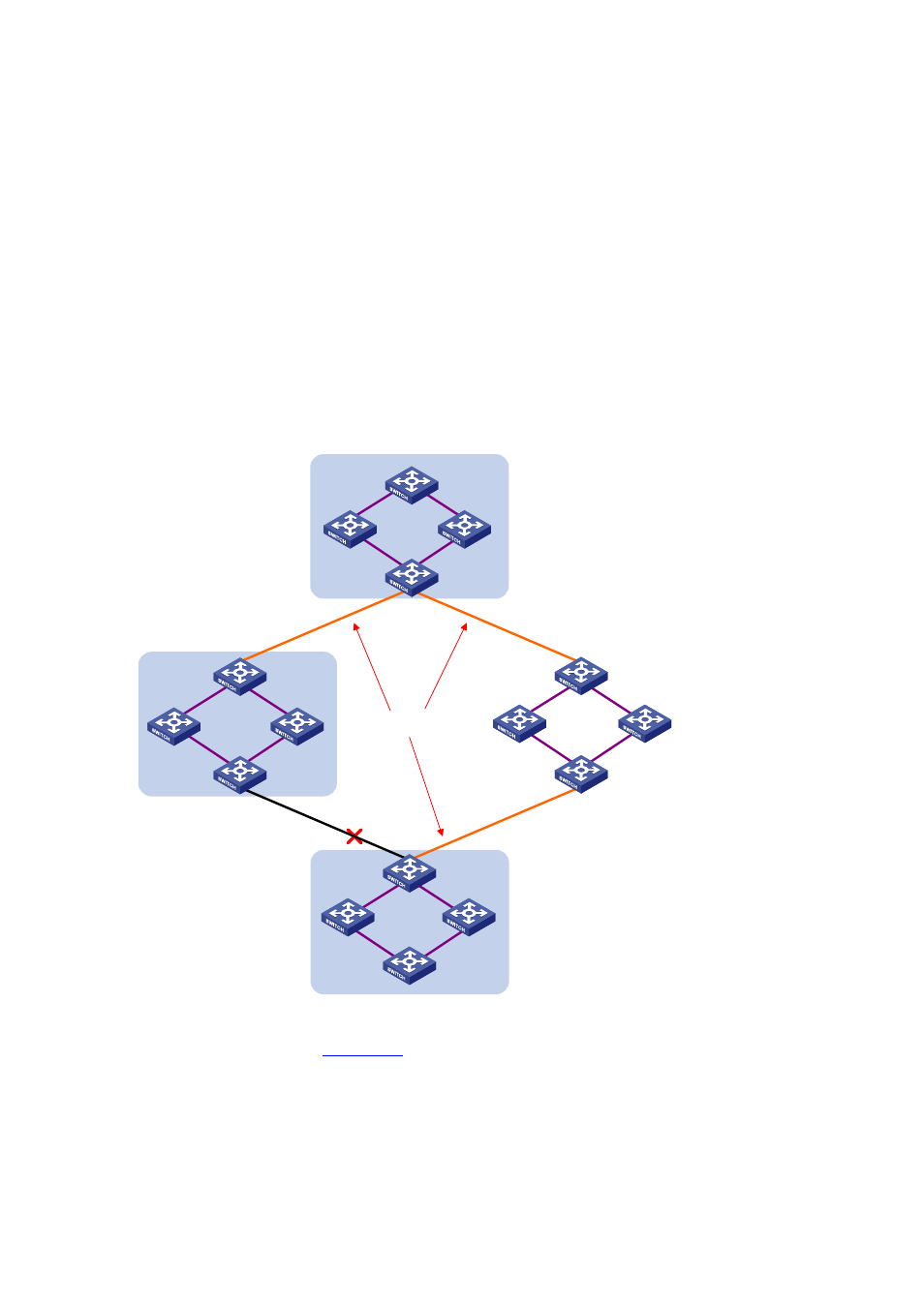
Basic Concepts in MSTP
Figure 13-4
Basic concepts in MSTP
CST
Region A0
VLAN 1 mapped to instance 1
VLAN 2 mapped to instance 2
Other VLANs mapped to CIST
Region B0
VLAN 1 mapped to instance 1
VLAN 2 mapped to instance 2
Other VLANs mapped to CIST
Region C0
VLAN 1 mapped to instance 1
VLAN 2 and 3 mapped to
instance 2
Other VLANs mapped to CIST
Region D0
VLAN 1 mapped to instance 1,
B as regional root bridge
VLAN 2 mapped to instance 2,
C as regional root bridge
Other VLANs mapped to CIST
BPDU
BPDU
BPDU
C
D
B
A
are running MSTP. This section explains some basic concepts
of MSTP.
MST region
A multiple spanning tree region (MST region) consists of multiple devices in a switched network and
the network segments among them. These devices have the following characteristics:
All are MSTP-enabled,