Network requirements, Network diagram, Configuration procedure – H3C Technologies H3C S7500E Series Switches User Manual
Page 76
4-23
[Sysname-Olt3/0/1] port link-type hybrid
[Sysname-Olt3/0/1] port hybrid vlan 1002 1003 tagged
# Configure Ethernet 2/0/1 as a Trunk port, and permit the packets of VLAN 1002 and VLAN 1003 to
pass.
[Sysname] interface Ethernet2/0/1
[Sysname-Ethernet2/0/1] port link-type trunk
[Sysname-Ethernet2/0/1] port trunk permit vlan 1002 1003
Multicast Configuration Example (in Multicast Control Mode)
Network requirements
Connect Ethernet 2/0/1 of the switch with a multicast source, and connect port OLT 3/0/1 of the OLT
with an ONU, which is bound to ONU 3/0/1:1, through an optical splitter. Attach two hosts, User 1 and
User 2, to ports UNI 1 and UNI 2 respectively.
It is required that User 1 and User 2 have different access rights to Channel 1 (225.1.1.1) and Channel
1 (225.1.2.1):
User 1 has full access to Channel 1 and 60-second preview access to Channel 2.
User 2 has access to Channel 2 only.
Network diagram
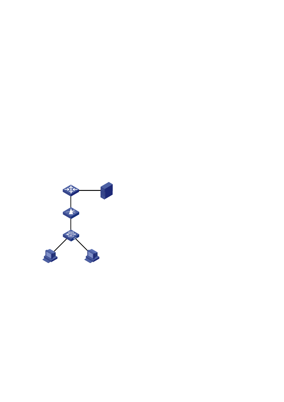
Figure 4-4
Network diagram for multicast configuration (in multicast control mode)
ONU
OLT
OLT3/0/1
POS
User1
UNI1
UNI2
User2
Eth2/0/1
Multicast Source
Configuration procedure
# Map the multicast addresses to multicast VLANs.
<Sysname> system-view
[Sysname] ftth
[Sysname-ftth] multicast vlan-id 1002 dest-ip 225.1.1.1
[Sysname-ftth] multicast vlan-id 1003 dest-ip 225.1.2.1
[Sysname-ftth] quit
#
Enable IGMP snooping globally.
[Sysname] igmp-snooping
[Sysname-igmp-snooping] quit
# Enable IGMP snooping in VLAN 1002 and VLAN 1003.
[Sysname] vlan 1002