Fiber backup configuration example, Network requirements, Network diagram – H3C Technologies H3C S7500E Series Switches User Manual
Page 52: Configuration procedure
3-10
[Sysname] interface olt3/0/1
[Sysname-Olt3/0/1] port-isolate enable
[Sysname-Olt3/0/1] quit
[Sysname] interface olt3/0/2
[Sysname-Olt3/0/2] port-isolate enable
[Sysname-Olt3/0/2] quit
# Display the isolation group information.
<Sysname> display port-isolate group
Port-isolate group information:
Uplink port support: NO
Group ID: 1
olt3/0/1 olt3/0/2
Fiber Backup Configuration Example
Network requirements
Add two OLT ports of the same EPON board to a fiber backup group one after the other.
Perform a manual switchover between the two OLT ports. When the master port is shut down, the
slave port becomes the new master port.
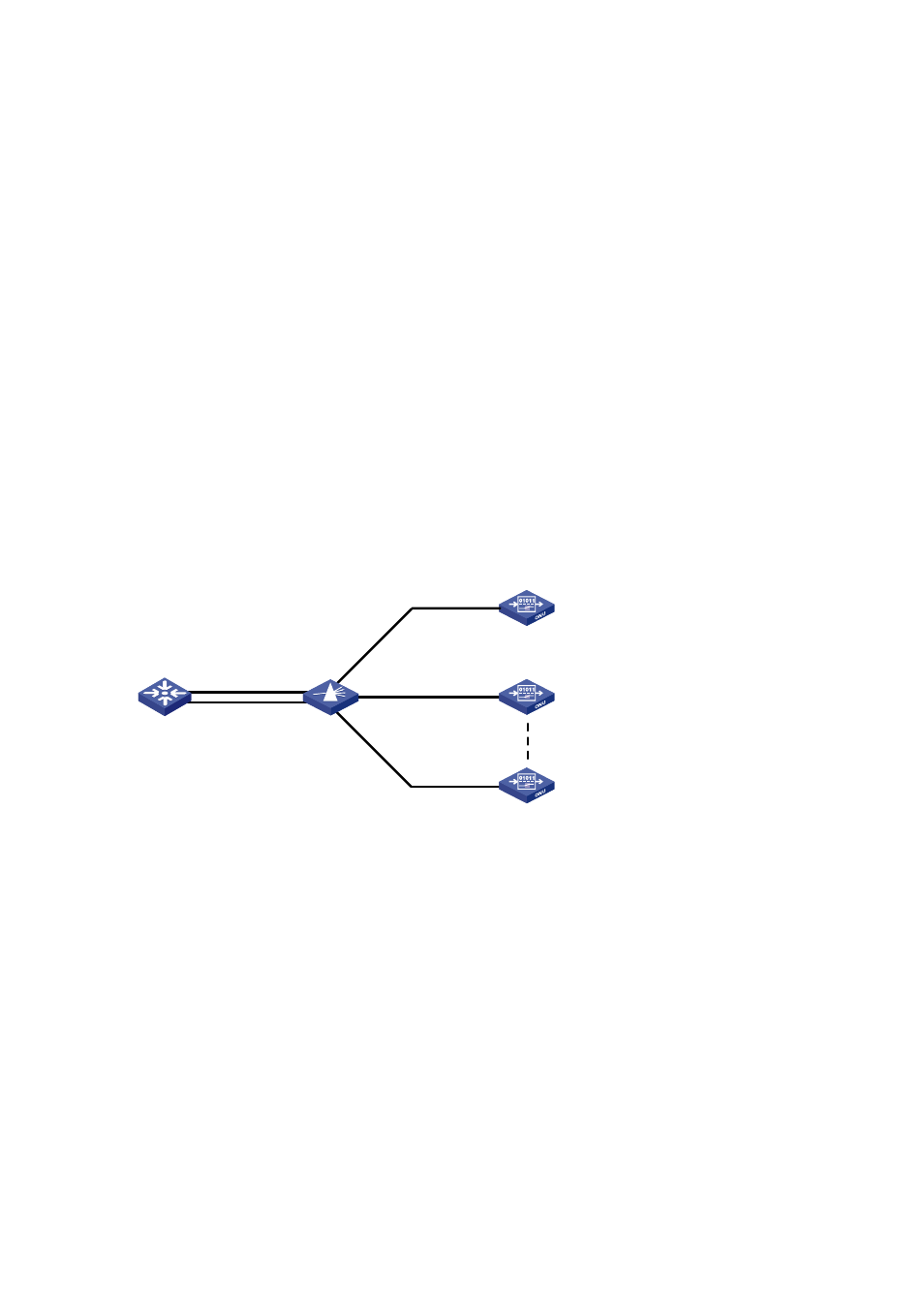
Network diagram
Figure 3-2
Network diagram for fiber backup group configuration
OLT3/0/1
OLT3/0/2
OLT
POS
ONU2
ONU1
ONUn
2:N
Configuration procedure
# Create fiber backup group 1.
<Sysname> system-view
[Sysname] ftth
[Sysname-ftth] fiber-backup group 1
Create group 1 successfully.
# Add port OLT 3/0/1 and then OLT 3/0/2 to fiber backup group 1. Thus, OLT 3/0/1 works as the master
port and OLT 3/0/2 the slave port.
[Sysname-fiber-group1] group member olt3/0/1
[Sysname-fiber-group1] group member olt3/0/2
[Sysname-fiber-group1] display fiber-backup group 1
fiber backup group 1 information:
Member Role State
-----------------------------------------
Olt3/0/1 MASTER ACTIVE
Olt3/0/2 SLAVE READY