Concepts and terms – H3C Technologies H3C S7500E Series Switches User Manual
Page 286
21-3
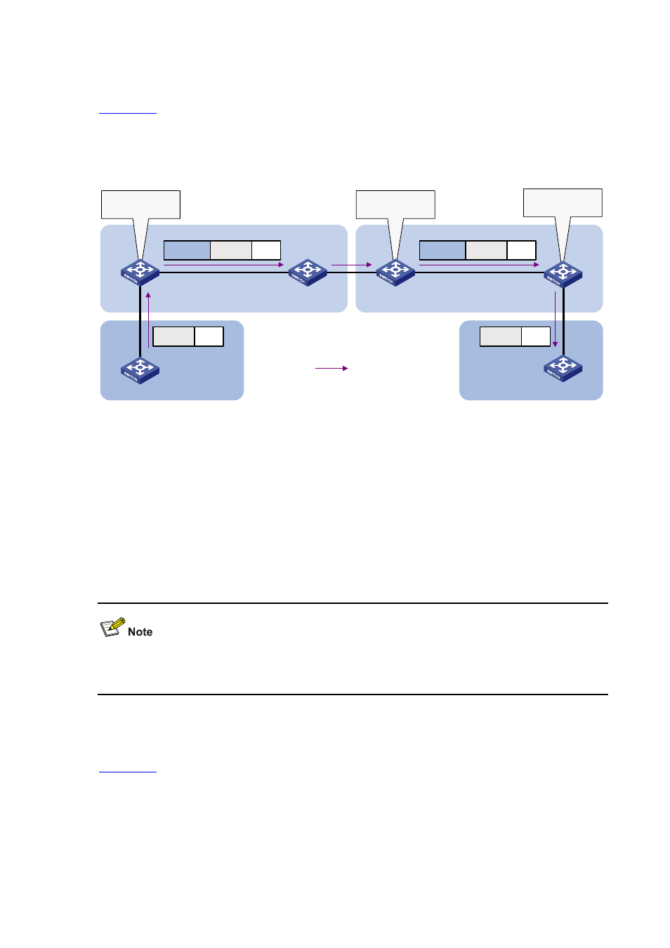
Application Scenario of One-to-Two and Two-to-Two VLAN Mapping
shows a typical application scenario in which two remote sites of VPN A, Site 1 and Site 2,
must communicate across two SP networks, SP 1 and SP 2.
Figure 21-2
Application scenario of one-to-two and two-to-two VLAN mapping
PE 1
VPN A
Site 1
SP 1
CE a1
VPN A
Site 2
SP 2
CE a2
Data
VLAN 2
Data
VLAN 10
VLAN 2
Data
VLAN 20
VLAN 3
Data
VLAN 3
Traffic
One-to-two VLAN
mapping
PE 2
PE 3
PE 4
Two-to-two VLAN
mapping
One-to-two VLAN
mapping
Site 1 and Site 2 are in VLAN 2 and VLAN 3 respectively. The VLAN assigned for VPN A is VLAN 10 in
the SP 1 network and VLAN 20 in the SP 2 network.
If Site 1 sends a packet to Site 2, the packet is processed as follows on the way to its destination:
1) When the packet tagged with VLAN 2 arrives at the edge of network SP 1, PE 1 tags the packet
with outer VLAN 10 by using one-to-two VLAN mapping.
2) When the double-tagged packet enters the SP 2 network, PE 3 replaces the outer VLAN tag
(VLAN 10) with VLAN 20. Because the packet is destined for Site 2 in VLAN 3, PE 3 also replaces
the inner tag (VLAN 2) of the packet with VLAN 3. This process is two-to-two VLAN mapping.
You can use QinQ to implement one-to-two VLAN mapping. For more information about QinQ, see
QinQ Configuration
in the Layer 2 - LAN Switching Configuration Guide.
Concepts and Terms
shows a simplified network to help explain the concepts and terms that you may encounter
when working with VLAN mapping.