Configuration procedure – H3C Technologies H3C S7500E Series Switches User Manual
Page 197
13-45
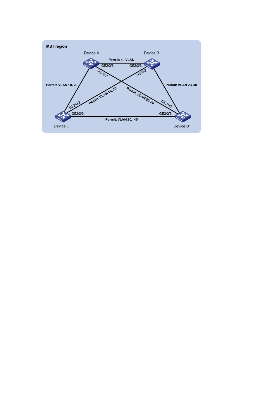
Figure 13-10
Network diagram for MSTP configuration
G
E
2/
0/
1
G
E
2/0
/1
G
E
2/
0/
1
G
E
2/0
/1
Configuration procedure
1) VLAN and VLAN member port configuration
Create VLAN 10, VLAN 20, and VLAN 30 on Device A and Device B respectively, create VLAN 10,
VLAN 20, and VLAN 40 on Device C, and create VLAN 20, VLAN 30, and VLAN 40 on Device D;
configure the ports on these devices as trunk ports and assign them to related VLANs. The detailed
configuration procedure is omitted.
2) Configuration on Device A
# Enter MST region view, configure the MST region name as example, map VLAN 10, VLAN 30, and
VLAN 40 to MSTI 1, MSTI 3, and MSTI 4 respectively, and configure the revision level of the MST
region as 0.
<DeviceA> system-view
[DeviceA] stp region-configuration
[DeviceA-mst-region] region-name example
[DeviceA-mst-region] instance 1 vlan 10
[DeviceA-mst-region] instance 3 vlan 30
[DeviceA-mst-region] instance 4 vlan 40
[DeviceA-mst-region] revision-level 0
# Activate MST region configuration.
[DeviceA-mst-region] active region-configuration
[DeviceA-mst-region] quit
# Specify the current device as the root bridge of MSTI 1.
[DeviceA] stp instance 1 root primary
# Enable MSTP globally.
[DeviceA] stp enable
3) Configuration on Device B
# Enter MST region view, configure the MST region name as example, map VLAN 10, VLAN 30, and
VLAN 40 to MSTI 1, MSTI 3, and MSTI 4 respectively, and configure the revision level of the MST
region as 0.
<DeviceB> system-view
[DeviceB] stp region-configuration