Network diagram, Configuration procedure – H3C Technologies H3C S7500E Series Switches User Manual
Page 266
19-8
Network diagram
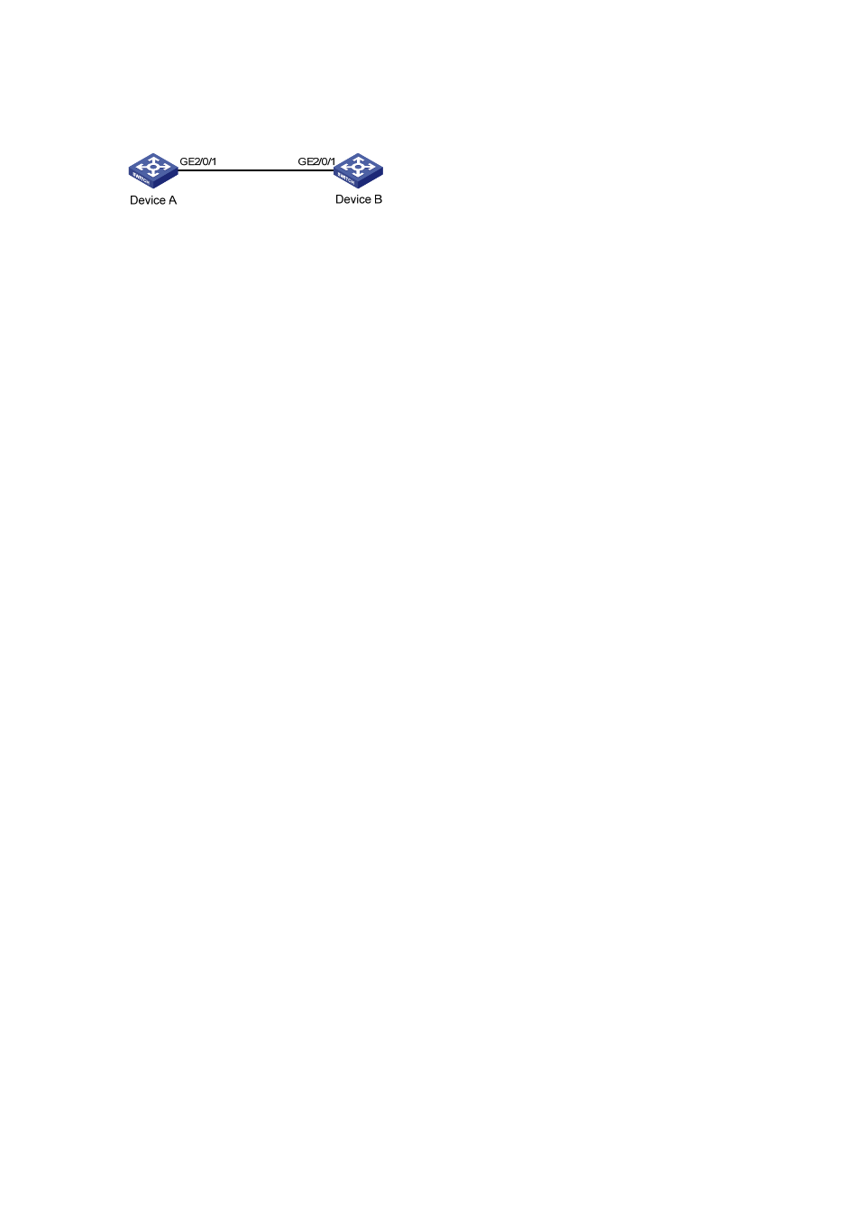
Figure 19-2
Network diagram for GVRP configuration
Configuration procedure
1) Configure
Device
A
# Enable GVRP globally.
<DeviceA> system-view
[DeviceA] gvrp
# Configure port GigabitEthernet 2/0/1 as a trunk port, allowing all VLANs to pass through.
[DeviceA] interface GigabitEthernet 2/0/1
[DeviceA-GigabitEthernet2/0/1] port link-type trunk
[DeviceA-GigabitEthernet2/0/1] port trunk permit vlan all
# Enable GVRP on GigabitEthernet 2/0/1, the trunk port.
[DeviceA-GigabitEthernet2/0/1] gvrp
[DeviceA-GigabitEthernet2/0/1] quit
# Create VLAN 2 (a static VLAN).
[DeviceA] vlan 2
2) Configure
Device
B
# Enable GVRP globally.
<DeviceB> system-view
[DeviceB] gvrp
# Configure port GigabitEthernet 2/0/1 as a trunk port, allowing all VLANs to pass through.
[DeviceB] interface GigabitEthernet 2/0/1
[DeviceB-GigabitEthernet2/0/1] port link-type trunk
[DeviceB-GigabitEthernet2/0/1] port trunk permit vlan all
# Enable GVRP on GigabitEthernet 2/0/1, the trunk port.
[DeviceB-GigabitEthernet2/0/1] gvrp
[DeviceB-GigabitEthernet2/0/1] quit
# Create VLAN 3 (a static VLAN).
[DeviceB] vlan 3
3) Verify the configuration
# Display dynamic VLAN information on Device A.
[DeviceA] display vlan dynamic
Now, the following dynamic VLAN exist(s):
3
# Display dynamic VLAN information on Device B.
[DeviceB] display vlan dynamic
Now, the following dynamic VLAN exist(s):
2