Network diagram, Configuration procedure – H3C Technologies H3C S7500E Series Switches User Manual
Page 281
20-12
Network diagram
Figure 20-4
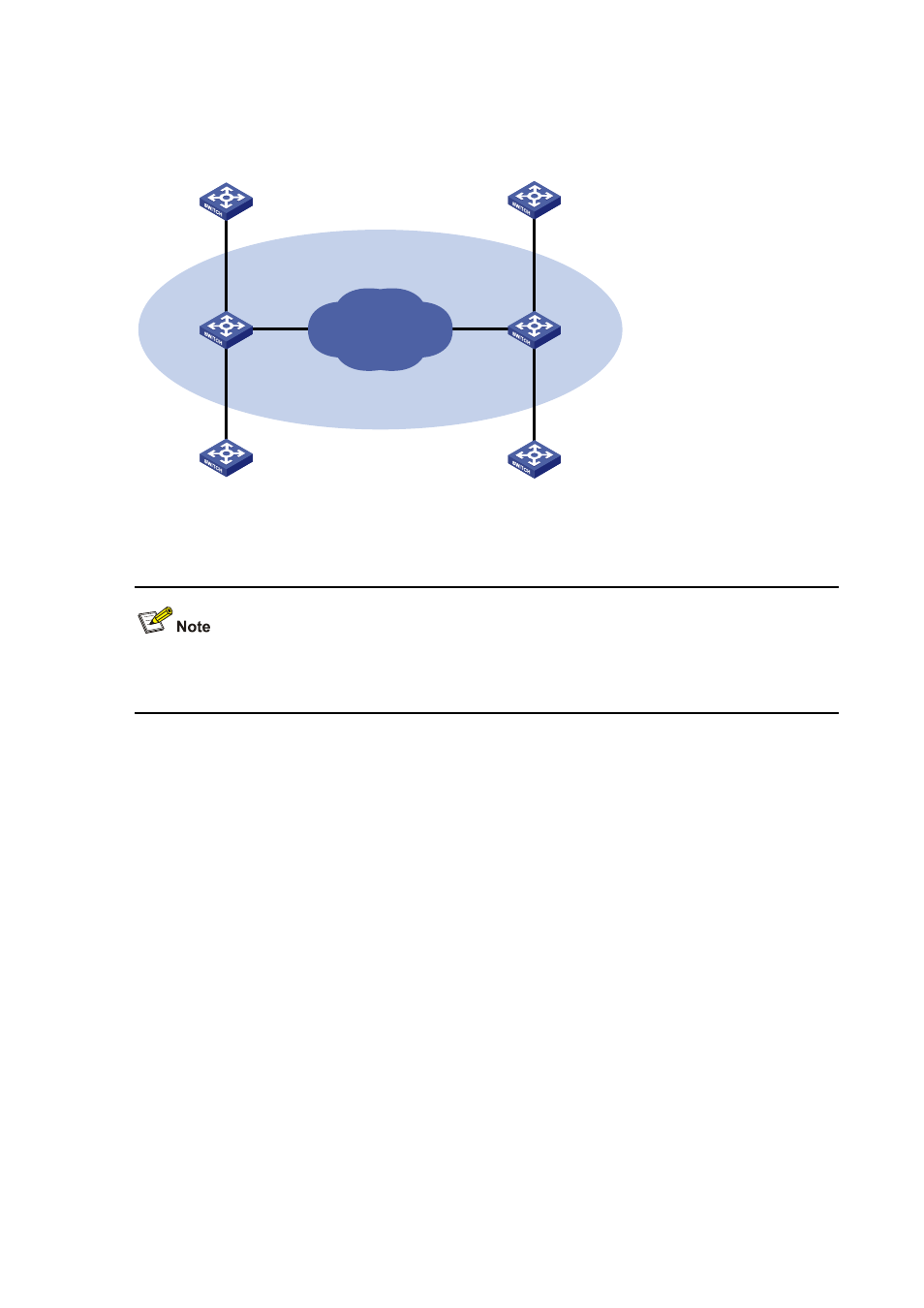
Network diagram for QinQ configuration
GE2/0/1
GE2/0/2
GE2/0/3
GE2/0/1
GE2/0/2
VLAN 10, VLAN 20
VLAN 10
VLAN 20
Customer B
Customer A
Customer C
Provider B
Provider A
Public network
VLAN 1000/2000/3000
TPID=0x8200
Customer D
GE2/0/3
Configuration procedure
With this configuration, the user must allow the QinQ packets to pass between the devices of the
service providers.
1) Configuration on Provider A
# Enter system view.
<ProviderA> system-view
Configuration on GigabitEthernet 2/0/1
# Configure the port as a hybrid port permitting frames of VLAN 1000, VLAN 2000, and VLAN 3000 to
pass through with the outer VLAN tag removed.
[ProviderA] interface gigabitethernet 2/0/1
[ProviderA-GigabitEthernet2/0/1] port link-type hybrid
[ProviderA-GigabitEthernet2/0/1] port hybrid vlan 1000 2000 3000 untagged
# Configure VLAN 3000 as the default VLAN of GigabitEthernet 2/0/1, and enable basic QinQ on
GigabitEthernet 2/0/1. As a result, the frames received on the port are tagged with the outer VLAN tag
3000.
[ProviderA-GigabitEthernet2/0/1] port hybrid pvid vlan 3000
[ProviderA-GigabitEthernet2/0/1] qinq enable
[ProviderA-GigabitEthernet2/0/1] quit
# Create a class A10 to match frames of VLAN 10 of Customer A.
[ProviderA] traffic classifier A10
[ProviderA-classifier-A10] if-match customer-vlan-id 10
[ProviderA-classifier-A10] quit