Onu rstp configuration example, Network requirements, Network diagram – H3C Technologies H3C S7500E Series Switches User Manual
Page 74: Configuration procedure
4-21
[Sysname-Olt3/0/1] quit
[Sysname] interface onu 3/0/1:1
[Sysname-Onu3/0/1:1] bind onuid 000f-e200-0031
[Sysname-Onu3/0/1:1] quit
[Sysname] interface onu 3/0/1:2
[Sysname-Onu3/0/1:2] bind onuid 000f-e200-3749
# When the two ONUs are up, display the binding information of the ONUs.
<Sysname> display onuinfo interface Olt 3/0/1
ONU Mac Address LLID Dist(M) Port Board/Ver Sft/Epm State Aging
000f-e200-0031 1 <50 Onu3/0/1:1 ET704-A-L/B 110/100 Up N/A
000f-e200-3749 2 <50 Onu3/0/1:2 ET704-A-L/B 110/100 Up N/A
--- 2 entries found ---
ONU RSTP Configuration Example
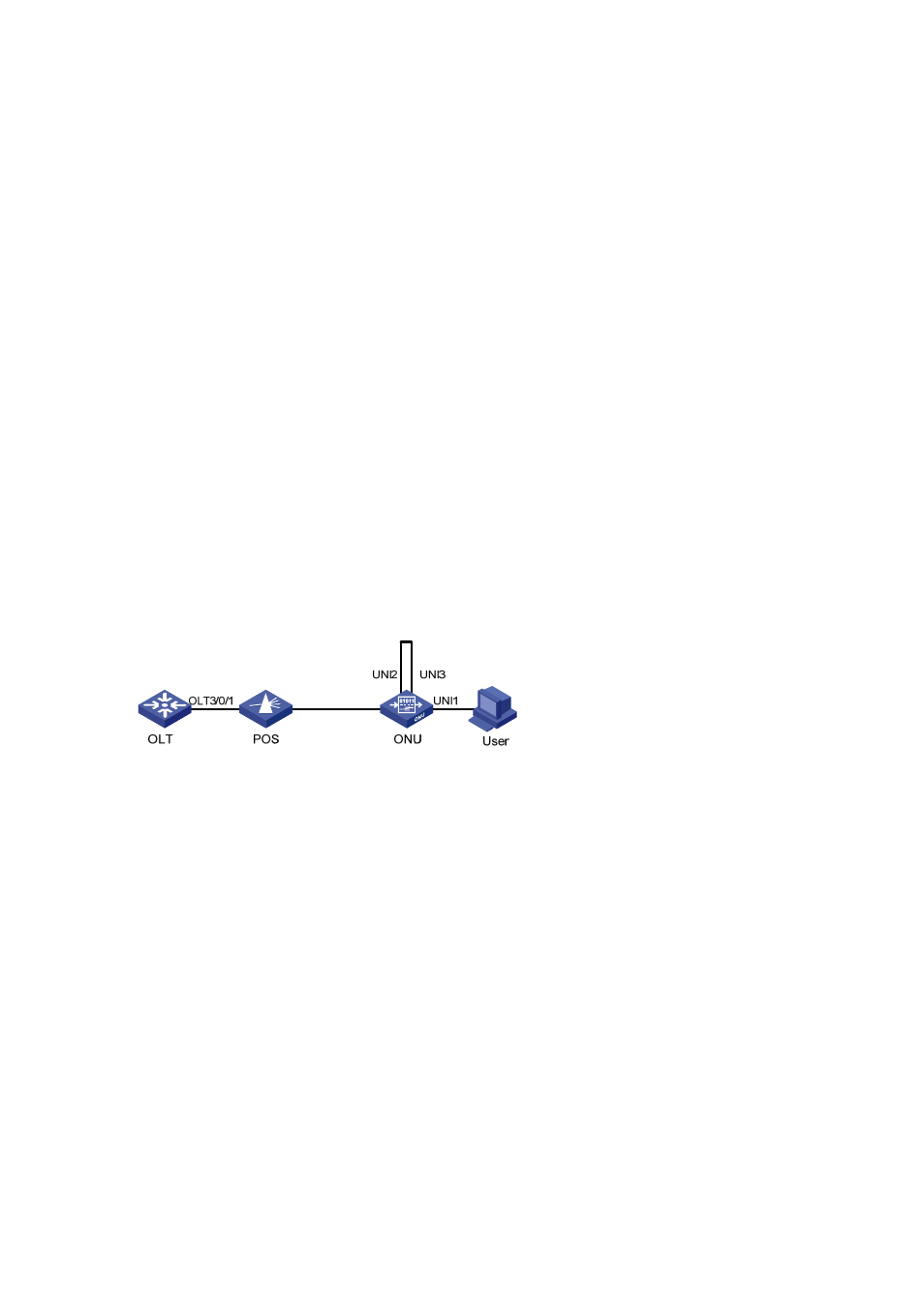
Network requirements
A user PC is attached to UNI 1. If UNI 2 and UNI 3 are interconnected by mistake while RSTP is
disabled on the ONU, broadcast storm will occur between UNI 2 and UNI 3 when the user pings
an IP address for which no ARP entry exists on the PC.
Enabling RSTP on the ONU can suppress such a problem.
Network diagram
Figure 4-2
Network diagram for ONU RSTP configuration
Configuration procedure
# Enable RSTP on the ONU to suppress the broadcast storm between UNI 2 and UNI 3.
<Sysname> system-view
[Sysname] interface onu 3/0/1:1
[Sysname-Onu3/0/1:1] onu-protocol stp enable
Multicast Configuration Example (in IGMP Snooping Mode)
Network requirements
Connect Ethernet 2/0/1 of the switch with a multicast source, and connect port OLT 3/0/1 of the
OLT with an ONU, which is bound to ONU 3/0/1:1, through an optical splitter. Attach two hosts,
User 1 and User 2, to ports UNI 1 and UNI 2 respectively.
It is required that User 1 has access to channels from 225.1.2.1 to 225.1.2.255, and User 2 has
access to channels from 225.1.3.1 to 225.1.3.255.