Ethernet (ip details) screen, Ethernet (ip details) screen -24 – Verilink WANsuite 6x30 (34-00315.B) Product Manual User Manual
Page 122
4-24
W A N s u i t e 6 x 3 0
D T R A larm C on tro l
Lets you set DTR Alarm Control parameters. Selecting “Enable” allows the
unit to go into alarm on loss of DTR, which occurs when the Serial port
detects that the DTR signal is low.
Values: Enable, Disable
Default: Disable
D T R A la rm S ta tu s
Lets you view the current DTR Alarm status.
F o rm a t
Selects the port’s operating mode.
Values: Sync, Async
Default: Sync
C u rren t P in S ta tu s
Shows the status of the DTE Serial port pins.
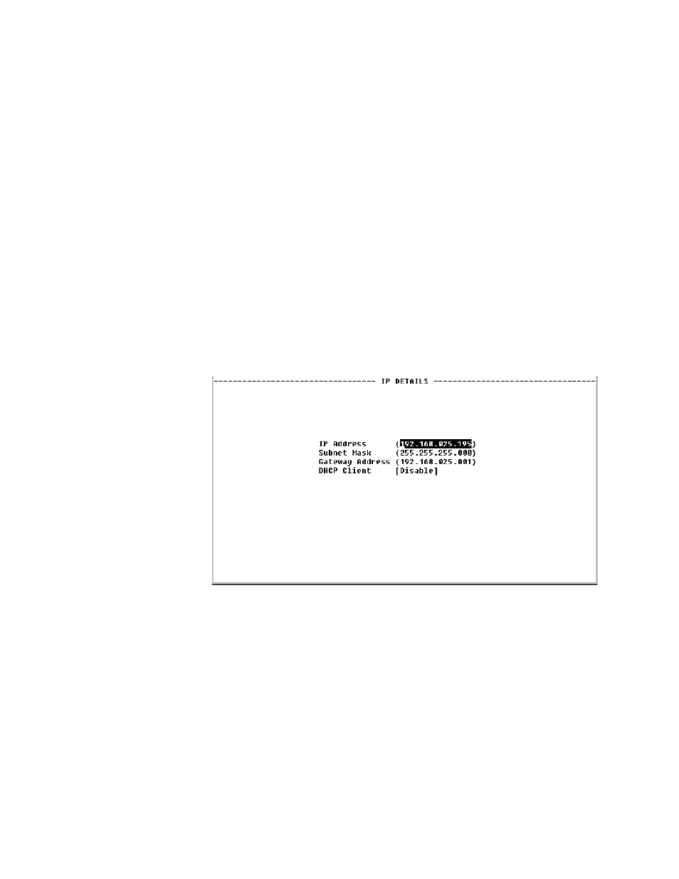
Ethernet (IP Details) Screen
If you select “Ethernet” from the Interfaces screen, you will bring up an IP
Details screen (Figure 4.19) that lets you view and/or modify the IP
parameters listed below.
Figure 4.19
IP Details Screen
IP A d d ress
A unique Network address assigned to this unit.
S u b n et M a sk
Defines the Network portion of the unit’s IP address.
G a tew ay A d d ress
IP address of the default gateway (router) on the LAN side of the unit.
D H C P C lien t
If DHCP Client is enabled at power-up, the unit will request its IP, Mask, and
Gateway addresses from a DHCP server located on the LAN side of the unit,
and the unit will use these addresses. If the DHCP request is unsuccessful, the
unit will use the configured addresses shown on this screen.