Verilink WANsuite 6x30 (34-00315.B) Product Manual User Manual
Page 44
3-16
W A N s u i t e 6 x 3 0
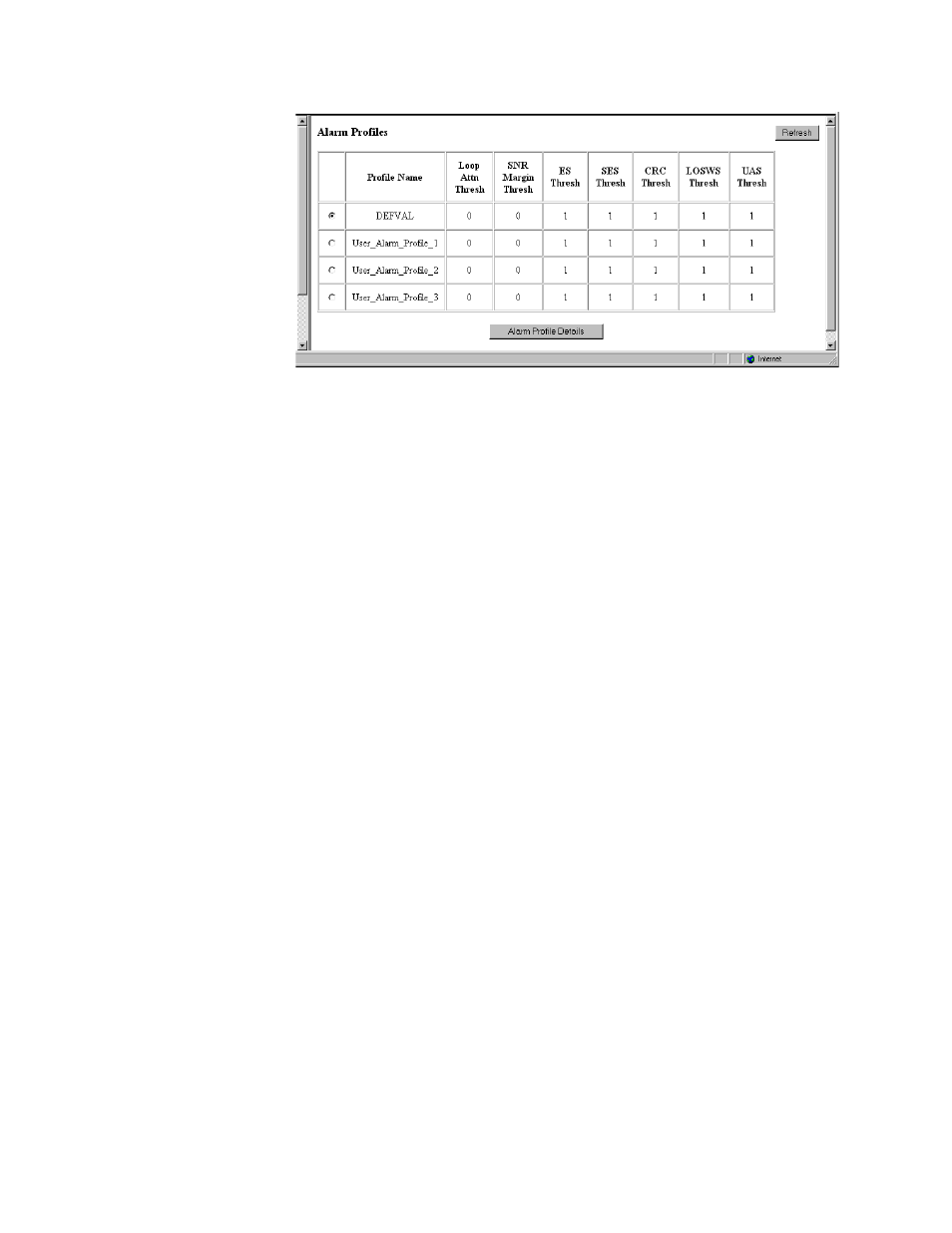
Figure 3.13
Alarm Profiles Screen
The Alarm Profiles screen displays the current status of endpoint alarms.
Information is displayed for the following alarm parameters:
E n d p o in t A la rm
C on fig P rofile N a m e
Displays the unique index associated with this Endpoint Alarm profile.The
values are obtained from the alarm configuration profile referenced by this
object. The value of this object is the index of the referenced profile in the
Line Alarm Configuration Profile Table, or NULL (a string of length 0). If
the value is NULL, the endpoint uses the default Alarm Configuration Profile
for the associated span. The default value of this object is NULL.
E n d p oin t T h resh L oo p
A ttn
Indicates the loop attenuation threshold has been reached/exceeded for the
selected segment endpoint.
E n d p oin t T h resh S N R
M argin
Indicates the Signal-to-Noise Ratio margin threshold has been reached/
exceeded for the selected segment endpoint.
E n d p oin t T h resh E S
Indicates the Errored Seconds threshold has been reached/exceeded for the
selected segment endpoint.
E n d p oin t S E S
Indicates the Severely Errored Seconds threshold has been reached/exceeded
for the selected segment endpoint.
E n d p oin t T h resh C R C
Indicates the Cyclic Redundancy Check anomalies threshold has been
reached/exceeded for the selected segment endpoint.
E n d p o in t T h resh
L O S W S
Indicates the Loss of Sync Word Second threshold has been reached/exceeded
for the selected segment endpoint.
E n d p oin t T h resh U A S
Indicates the Unavailable Seconds Threshold has been reached/exceeded for
the selected segment endpoint.
In addition to the alarm status table, the Alarm Profiles screen has an “Alarm
Profile Details” button.