Rear panel connections, Rear panel connections -5 – Verilink WANsuite 6x30 (34-00315.B) Product Manual User Manual
Page 21
A b o u t t h e W A N s u i t e 6 x 3 0
1-5
The front panel’s five LED status indicators are described below:
The user-activated input control buttons are described below:
*The
CONFIG
button must be held until the
MODE
LED lights amber and remains illuminated for the
default configuration to take effect.
Rear Panel Connections
The rear panels of the WANsuite 6x30 product family differ from unit to unit.
Each is described below.
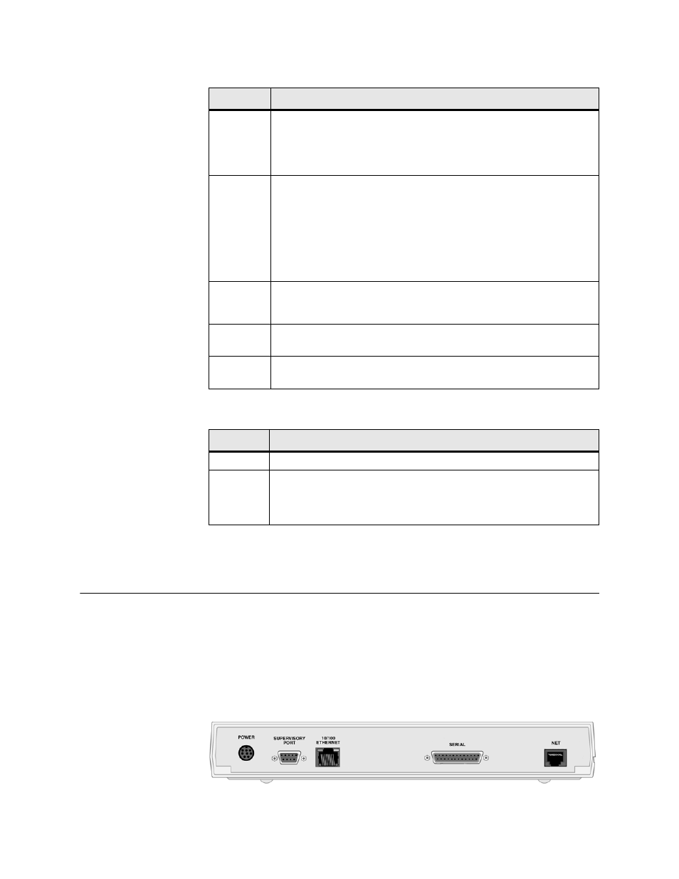
The WANsuite 6130 has five connectors. From left to right these are as
follows:
POWER
,
SUPERVISORY PORT
,
10/100 ETHERNET
,
SERIAL
INTERFACE
,
and
NET
as shown in Figure 1.2 below.
Figure 1.2
WANsuite 6130 Rear Panel
Indicator
Description
MODE
Normally, this indicator lights green.
The indicator lights amber while configuration is being set by the front panel
buttons or when the configuration is changed by SNMP or through the Web
interface. The indicator will remain amber until the changed configuration is
saved; it will revert to green when the new configuration has been saved.
NET
This indicator is off (not illuminated) when the Network port has not been
configured.
The indicator lights green when the Network port link is up and the ATM
protocol is established.
The indicator lights red when the Network port link is down and the ATM
protocol is not established.
The indicator lights amber when the Network port link is up but the ATM
protocol is not established.
SERIAL
This indicator is off (not illuminated) when the port has not been configured.
The indicator lights green when the serial port is active.
The indicator lights amber when the serial port is not active.
ALARM
This indicator lights red if an alarm condition exists.
The indicator lights amber if a “yellow” alarm condition exists.
POWER
This indicator lights green when power is applied to the unit.
The indicator lights amber in test modes (Port looped or BERT active).
Button
Description
RESET
Provides a hardware reset to the unit.
CONFIG
Sets the unit back to its factory default Ethernet or HDLC configuration; this is
the same as a maintenance reset.
To initiate this function, you must press and hold the
CONFIG
button during a
power-up sequence.*