Restoring factory default network settings – ProSoft Technology ILX34-AENWG User Manual
Page 100
Diagnostics and Troubleshooting
ILX34-AENWG ♦ Point I/O Platform
User Manual
Wireless POINT I/O Adapter
Page 100 of 177
ProSoft Technology, Inc.
August 16, 2013
4.7.1 Cable Connections
Ethernet Cable Specifications
The recommended cable is category 5 or better. A category 5 cable has four
twisted pairs of wire that are color-coded and cannot be swapped. The radio
uses only two pairs. One pair uses pins 1 and 2, and the second pair uses pins 3
and 6.
Use a straight-through cable when connecting the radio to an Ethernet hub or
a 10/100 Base-T Ethernet switch. Straight-through cables are used in most
cases.
Use a cross-over cable when connecting the Ethernet radio directly to any
device that is NOT a switch or a hub (for example, a direct connection to a
PC, PLC, or printer).
Ethernet cabling is like U.S. telephone cables, except that it has eight
conductors. Some hubs have one input that can accept either a straight-through
or crossover cable, depending on the switch position. In this case, you must
ensure that the switch position and cable type agree.
Refer to Ethernet Cable Configuration (page 100) for a diagram of how to
configure Ethernet cable.
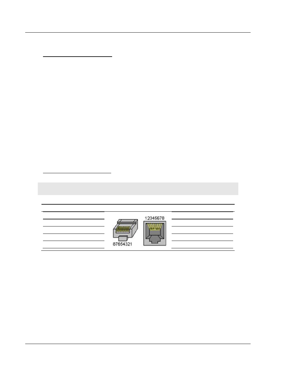
Ethernet Cable Configuration
Note: The standard connector view shown is color-coded for a straight-through cable.
Crossover cable
Straight- through cable
RJ-45 PIN
RJ-45 PIN
1 Rx+
3 Tx+
2 Rx-
6 Tx-
3 Tx+
1 Rx+
6 Tx-
2 Rx-
RJ-45 PIN
RJ-45 PIN
1 Rx+
1 Tx+
2 Rx-
2 Tx-
3 Tx+
3 Rx+
6 Tx-
6 Rx-
4.8
Restoring Factory Default Network Settings
Restoring the network settings to factory defaults depends on the version of
firmware in your ILX34.
Firmware Versions 3.4.xxx
1 Turn module power off.
2 Change thumbwheels to 888.
3 Turn module power on.