ProSoft Technology ILX34-AENWG User Manual
Page 71
ILX34-AENWG ♦ Point I/O Platform
About the Example Applications
Wireless POINT I/O Adapter
User Manual
ProSoft Technology, Inc.
Page 71 of 177
August 16, 2013
C = configuration, I = input, O = output
Use the controller tags in your ladder program to read input data or write output
data.
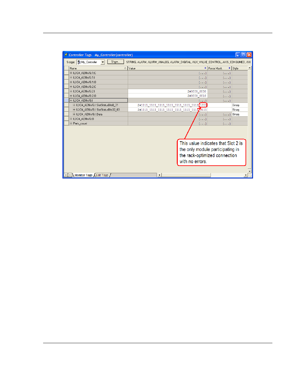
Slot Status Bits: The Slot Status bits display the connection status for each of
the POINT I/O modules that use a rack-optimized connection.
Bit 0 is reserved for the adapter and always reports a value of 1.
Each of the other bits (1 to 63) correspond to a POINT I/O module that you
install in the POINT I/O backplane.
In this example, we configured the ILX34-AENWG adapter for both rack-
optimized and direct connections.
The slot status bits indicate that the module in slot 2 is operating correctly:
o
0=module participating with no errors and
o
1=module not participating or connection error (typically, module
removed/missing)