E 166) – ProSoft Technology ILX34-AENWG User Manual
Page 166
Reference
ILX34-AENWG ♦ Point I/O Platform
User Manual
Wireless POINT I/O Adapter
Page 166 of 177
ProSoft Technology, Inc.
August 16, 2013
Cable Type
Cable loss/
100' (dB)
Minimum
length (feet)
Loss (dB)
Maximum
length (feet)
Loss (dB)
LDF4-50A
3.9
167
6.5
512
20
LDF5-50A
2
325
6.5
1000
20
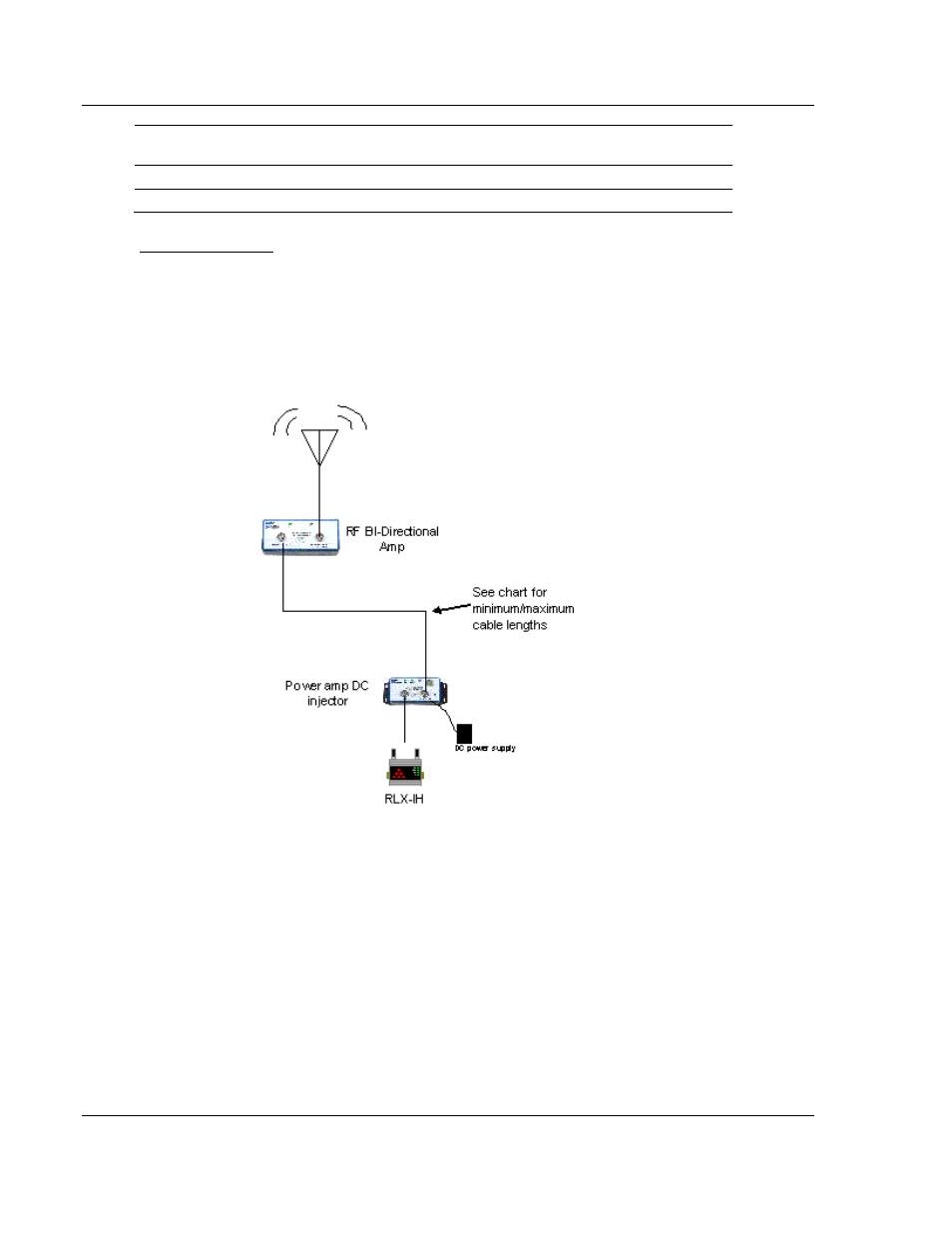
Amplifier diagram
The following illustration shows proper installation of the amplifier and its power
supply. The DC injector can be located by the radio, and the amplifier should be
at the antenna. The bi-directional amplifier is weather proof and can be mounted
outdoors. Refer to the bi-directional amplifier instructions for more information.
Refer to the Adding bi-directional amplifiers (page 165) for minimum and
maximum cable lengths.
6.5.9 Antenna location, spacing, and mounting
Consider the following points regarding antenna location, spacing, and mounting:
When placing antennas, ensure a clear line of sight between the master
radio's antenna and all of the other radio antennas.
If the site base contains obstructing terrain or structures, mount the antenna
on a tower or rooftop to provide a line-of-sight path. The line-of-sight
consideration becomes more important as the transmission path becomes
longer.
Mount the antennas as high off the ground as is practical. The higher an
antenna is above the ground, the greater its range.