ProSoft Technology ILX34-AENWG User Manual
Page 164
Reference
ILX34-AENWG ♦ Point I/O Platform
User Manual
Wireless POINT I/O Adapter
Page 164 of 177
ProSoft Technology, Inc.
August 16, 2013
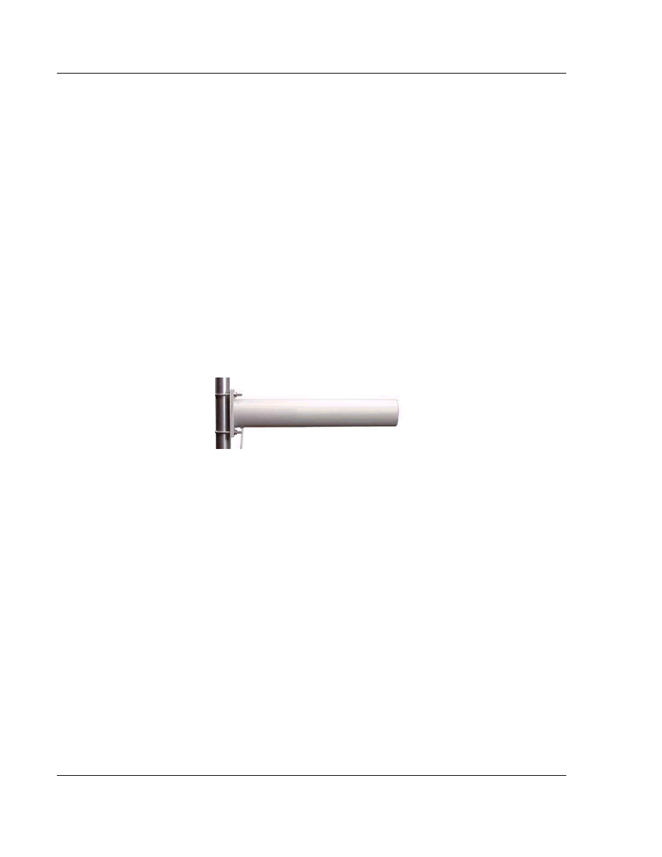
6.5.6 Yagi Array Antenna
A yagi antenna is composed of an array of linear elements, each parallel to one
another and attached perpendicular to and along the length of a metal boom. The
feed is attached to only one of the elements. Elements on one side of the fed
element are longer and act as reflectors; elements on the other side are shorter
and act as directors. This causes the antenna to radiate in a beam out of the end
with the shorter elements. The pattern depends on the overall geometry,
including the number of elements, element spacing, element length, and so on.
Sometimes the antenna is enclosed in a protective tube hiding the actual
antenna geometry.
The Antenna Pattern (page 161) is a beam pointed along the boom toward the
end with the shorter elements. The beamwidth varies with antenna geometry but
generally is proportional to the length (where longer length produces a narrower
beam).
The Antenna Gain (page 162) varies with antenna geometry but generally is
proportional to the length (where longer length produces higher gain). Typical
values are 6 to 15dBi.
The antenna polarity is Linear (parallel to the elements, perpendicular to the
boom).
Refer to the Antenna Types overview section for other types of approved
antennas.
6.5.7 Parabolic reflector antennas
A parabolic reflector antenna consists of a parabolic shaped dish and a feed
antenna located in front of the dish. Power is radiated from the feed antenna
toward the reflector. Due to the parabolic shape, the reflector concentrates the
radiation into a narrow pattern, resulting in a high- gain beam.
The antenna pattern is a beam pointed away from the concave side of the dish.
Beamwidth and antenna gain vary with the size of the reflector and the antenna
construction. Typical gain values are 15 to 30 dBi.