Bit phy interface signals – Altera IP Compiler for PCI Express User Manual
Page 227
Chapter 14: External PHYs
14–7
External PHY Support
August 2014
Altera Corporation
IP Compiler for PCI Express User Guide
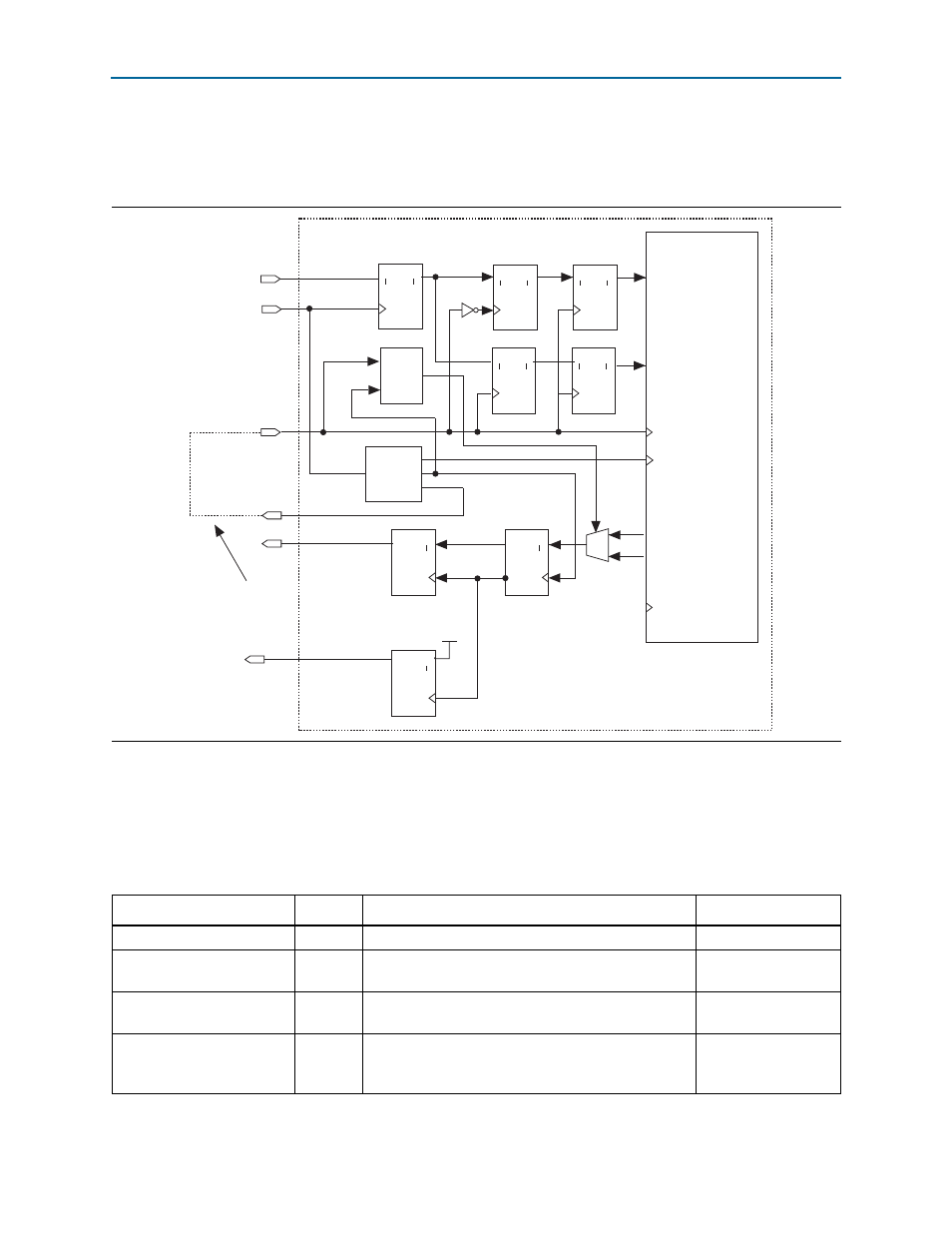
An edge detect circuit detects the relationships between the 125 MHz clock and the
250 MHz rising edge to properly sequence the 16-bit data into the 8-bit output
register.
16-bit PHY Interface Signals
summarizes the external I/O signals for the 16-bit PIPE interface modes.
Depending on the number of lanes selected and whether the PHY mode has a TXClk,
some of the signals may not be available as noted.
Figure 14–6. 8-bit SDR Mode with 250 MHz Source Synchronous Transmit Clock
IP Compiler
for PCI Express
clk125_zero
tlp_clk
refclk
rxdata
clk125_out
clk125_in
ENB
Q
Q
A
1
D
4
ENB
Q
Q
A
1
D
4
txdata
ENB
A
D
Q
1
Q
4
Mode 4
PLL
ENB
Q
Q
A
1
D
4
txdata_h
txdata_l
Edge
Detect
& Sync
clk250_early
External connection
in user logic
ENB
A
D
Q
1
Q
4
ENB
A
D
Q
1
Q
4
ENB
A
D
Q
1
Q
4
ENB
A
D
Q
1
Q
4
rxdata_h
rxdata_l
refclk (pclk) 250 MHz
clk250_early
txclk (~refclk)
Table 14–2. 16-bit PHY Interface Signals (Part 1 of 3)
Signal Name
Direction
Description
Availability
pcie_rstn
I
IP Compiler for PCI Express reset signal, active low.
Always
phystatus_ext
I
PIPE interface phystatus signal.Signals the completion
of the requested operation
Always
powerdown_ext[1:0]
O
PIPE interface powerdown signal. Used to request that
the PHY enter the specified power state.
Always
refclk
I
Input clock connected to the PIPE interface pclk signal
from the PHY. 125 MHz clock that clocks all of the
status and data signals.
Always