Generation of pci express interrupts, The most significant bits of, Figure 4–12 – Altera IP Compiler for PCI Express User Manual
Page 82
4–24
Chapter 4: IP Core Architecture
PCI Express Avalon-MM Bridge
IP Compiler for PCI Express User Guide
August 2014
Altera Corporation
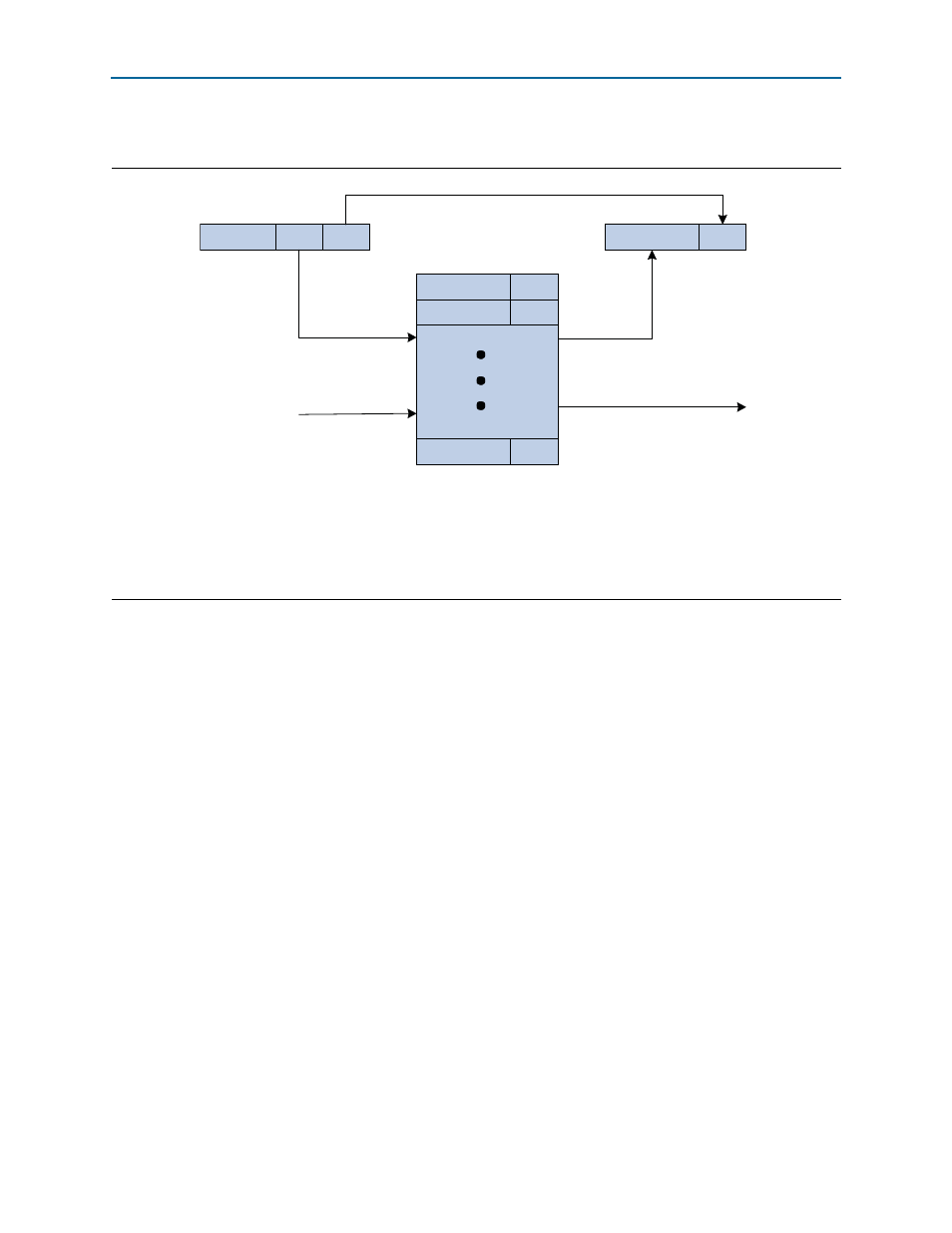
depicts the Avalon-MM-to-PCI Express address translation process.
Generation of PCI Express Interrupts
The PCI Express Avalon-MM bridge supports MSI or legacy interrupts. The completer
only, single dword variant includes an interrupt generation module. For other
variants with the Avalon-MM interface, interrupt support requires instantiation of the
CRA slave module where the interrupt registers and control logic are implemented.
The Qsys-generated PCI Express Avalon-MM bridge supports the Avalon-MM
individual requests interrupt scheme: multiple input signals indicate incoming
interrupt requests, and software must determine priorities for servicing simultaneous
interrupts the IP Compiler for PCI Express receives on the Avalon-MM interface.
In the Qsys-generated IP Compiler for PCI Express, the RX master module port has as
many as 16 Avalon-MM interrupt input signals (RXmirq_irq[
<n>
:0]
, where
<n>
≤
15)) .
Each interrupt signal indicates a distinct interrupt source. Assertion of any of these
signals, or a PCI Express mailbox register write access, sets a bit in the PCI Express
interrupt status register. Multiple bits can be set at the same time; software determines
priorities for servicing simultaneous incoming interrupt requests. Each set bit in the
PCI Express interrupt status register generates a PCI Express interrupt, if enabled,
when software determines its turn.
Software can enable the individual interrupts by writing to the IP Compiler for PCI
Express
“Avalon-MM to PCI Express Interrupt Enable Register Address: 0x0050” on
through the CRA slave.
Figure 4–12. Avalon-MM-to-PCI Express Address Translation
Notes to
:
(1) N is the number of pass-through bits.
(2) M is the number of Avalon-MM address bits.
(3) P is the number of PCI Express address bits.
(4) Q is the number of translation table entries.
(5) Sp[1:0] is the space indication for each entry.
PCIe Address Q-1
SpQ-1
Space Indication
PCI Express address from Table Entry
becomes High PCI Express address bits
PCI Express Address
High
Low
P-1
N N-1
0
Low address bits unchanged
Avalon-MM-to-PCI Express
Address Translation Table
(Q entries by P-N bits wide)
PCIe Address 0
Sp0
PCIe Address 1
Sp1
Avalon-MM Address
High
Slave Base
Address
Low
M-1
31
M
N N-1
0
Table updates from
control register port
High Avalon-MM Address
Bits Index table