Root port testbench – Altera IP Compiler for PCI Express User Manual
Page 236
15–4
Chapter 15: Testbench and Design Example
Root Port Testbench
IP Compiler for PCI Express User Guide
August 2014
Altera Corporation
The testbench has several VHDL generics/Verilog HDL parameters that control the
overall operation of the testbench. These generics are described in
.
Root Port Testbench
The root port testbench is provided in the subdirectory <variation_name>_examples/
root_port/testbench
in your project directory. The top-level testbench is named
<variation_name>_rp_testbench.
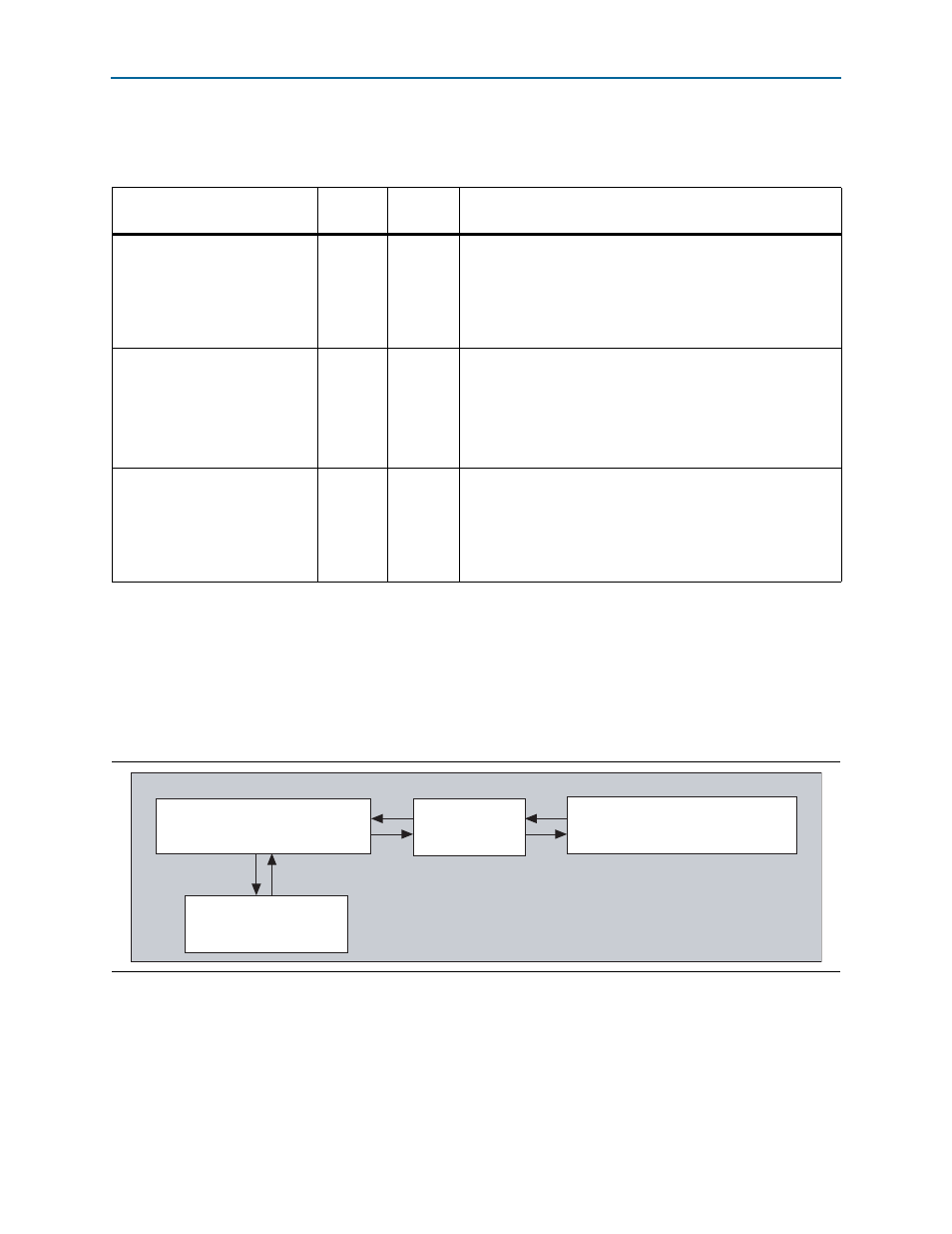
presents a high level view of the
testbench.
This testbench simulates up to an ×8 PCI Express link using either the PIPE interfaces
of the root port and endpoints or the serial interface. The testbench design does not
allow more than one PCI Express link to be simulated at a time. The top-level of the
testbench instantiates four main modules:
Table 15–1. Testbench VHDL Generics /Verilog HDL Parameters
Generic/Parameter
Allowed
Values
Default
Value
Description
PIPE_MODE_SIM
0 or 1
1
Selects the PIPE interface (PIPE_MODE_SIM=1) or the serial
interface (PIPE_MODE_SIM= 0) for the simulation. The PIPE
interface typically simulates much faster than the serial
interface. If the variation name file only implements the PIPE
interface, then setting PIPE_MODE_SIM to 0 has no effect and
the PIPE interface is always used.
NUM_CONNECTED_LANES
1,2,4,8
8
Controls how many lanes are interconnected by the testbench.
Setting this generic value to a lower number simulates the
endpoint operating on a narrower PCI Express interface than
the maximum.
If your variation only implements the ×1 IP core, then this
setting has no effect and only one lane is used.
FAST_COUNTERS
0 or 1
1
Setting this parameter to a 1 speeds up simulation by making
many of the timing counters in the IP Compiler for PCI Express
operate faster than specified in the PCI Express
specification.This parameter should usually be set to 1, but can
be set to 0 if there is a need to simulate the true time-out
values.
Figure 15–2. Testbench Top-Level Module for Root Port Designs
Root Port DUT
(altpcierd_pipe_phy)
PIPE Interconnection
Module x8
EP Model
(altpcietb_bfm_ep_example_chaining_pipen1b)
(<variation_name>_example_rp_pipen1b)
Testbench Top-Level
(<variation_name>_testbench)
Root Port BFM
(altpcietb_bfm_driver_rp)