Rear panel, Part ix–connections and ports – Teac SX-1 Reference Manual User Manual
Page 193
Part IX–Connections and Ports
TASCAM SX-1
Reference Manual
193
8
INSERT
Insert jacks fall before the channel’s
analog to digital converter. The jacks are of a stan-
dard stereo input type with the tip=send, ring=return,
and sleeve=ground.
9
LINE IN (BAL) [TRS]
These 1/4-inch
inputs accept balanced and unbalanced jacks. They
are used for line inputs and are of a standard wiring
(tip is hot).
A
MIX [XLR]
The XLR jacks are connected to
their respective mic preamps. The phantom power
switch for each group is directly above the XLR
jacks. The jacks follow standard wiring (pin 2 is hot).
WARNING
Connection of microphone cable and microphones: to
prevent hazard or damage, ensure that only micro-
phones designed to the IEC 268-15A standard are con-
nected.
Connexions des microphones et de leurs câbles: pour
éviter tout endommagement, s’assurer de vrancher
uniquement des microphone et des câbles de micro-
phone conçus selon la norme IEC 268-15A.
B
TRIM
These knobs control the gain for the
incoming signal. The gain goes from 0dB to +54dB.
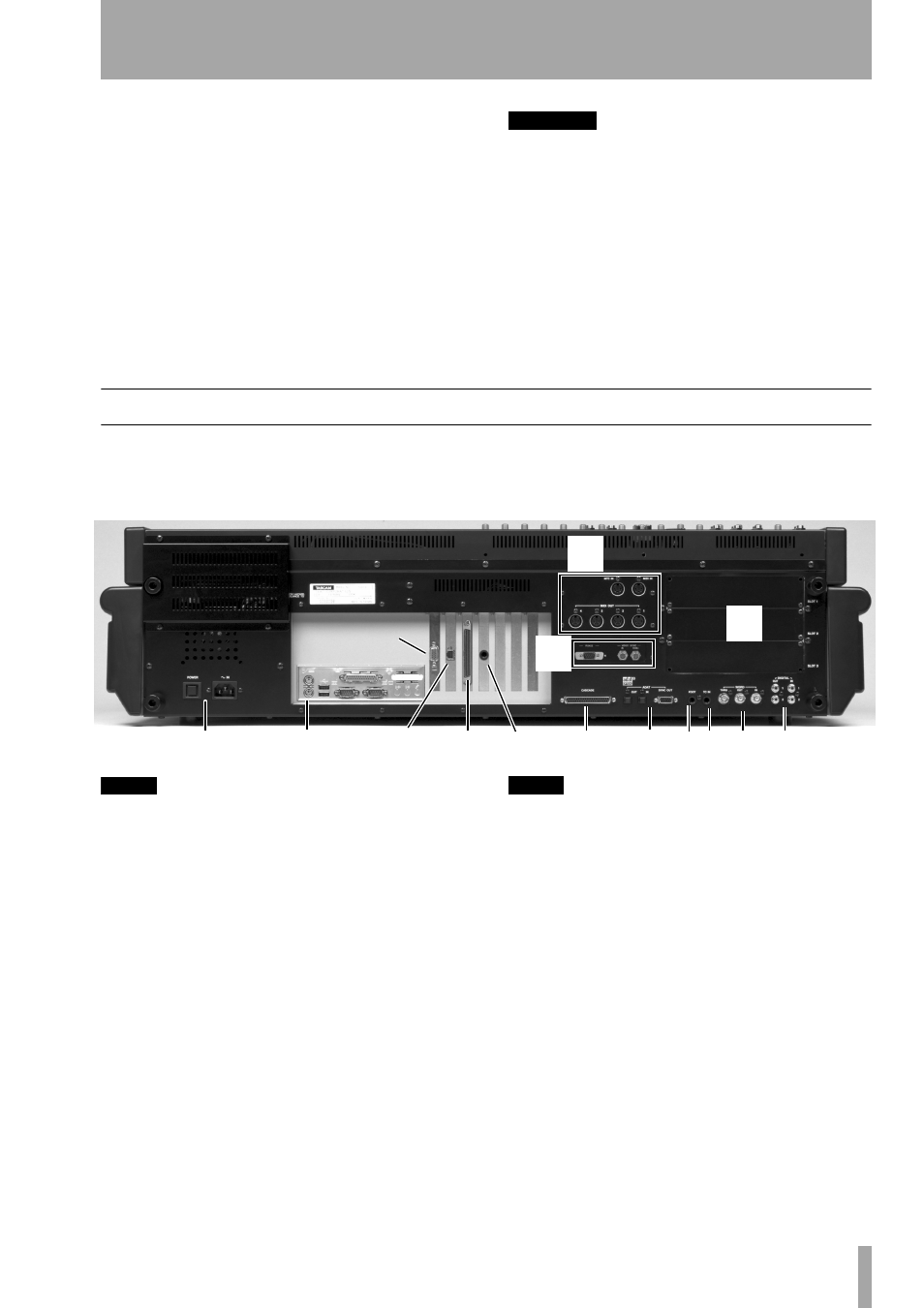
Rear Panel
The rear panel of the SX-1 is where all of the unit’s
peripheral ports are located, including MIDI, digital
I/O, clock sync, and Option Slots
NOTE
The position of some of the boards fitted in your SX-1
may differ slightly from the positions shown here..
There are many connections and ports on the SX-1’ s
rear. It is not necessary to understand all of them in
order to begin using the machine. For now, the areas
highlighted above (and explained below) are the
most important. (To learn more about the other con-
nections and ports, see the Owner’s Manual.)
1 Power
This is where the SX-1’s power cable
connects. An IEC Type II detachable power cable is
included with the unit. The
POWER
switch is used to
turn the unit on and off.
2 Peripheral Ports
The PS/2 keyboard and
mouse connect here. The port colored purple is for
the provided keyboard, while the green port is for the
provided mouse. The other included connections in
this section are reserved for future expansion.
NOTE
The SX-1 USB ports are disabled.
3 MIDI Ports
Here you will find
MIDI OUT
Ports A, B, C, and D. Connect these ports to the
MIDI inputs of your MIDI sound modules. Also in
this area is the
MIDI IN
, where you connect the output
of your MIDI controller, and a MIDI Time Code
(MTC) jack for reading incoming MTC (see “Trans-
port, Loop, Auto Punch” on page 31 for more about
synchronization).
4 SCSI Port
The SX1 comes equipped with a
68-pin Ultra Wide SCSI interface. You can use this
port to connect to compatible SCSI drives and
backup solutions.
5 VIDEO IN/THRU & Sony 9-pin
These
jacks are involved with synchronization. Connect a
Video sync signal (also called house sync or black-
burst) to the
VIDEO IN
.
VIDEO THRU
will pass that
1
2
4
B
6
7
8 9 A
C
3
D
5
VGA port
Ethernet
port