For an as2000 node – Verilink Access Manager 2000 (896-502037-001) Product Manual User Manual
Page 280
Monitoring and Troubleshooting Access Manager
8-10
Access Manager 2000 User Manual
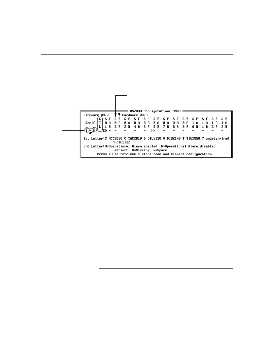
A typical Access System 2000 node configuration is shown below.
To have the maximum number of slots, each node can have up to 2
multiline and 4 dual-line shelves, numbered 1, 2, 3, and 4. The multiline
shelves have 13 slots for circuit elements, and the dual-line shelves have 2
slots for circuit elements.
In this screen, the slots are numbered S01 to S13, reading from left to
right. Paired with each of these slots is FAR, which designates the far-end
CSU if the near-end slot holds a CSU circuit element. But FAR should be
disregarded if the near-end slot holds a DIU or a TIU
Finally, the first column to the right of the shelf number indicates the slot
of the node’s master controller (an NCC 2020 or CCC 1020). The node’s
master controller must always be in Shelf 1, Slot 1.
The near-end Access System 2000 circuit element status is displayed with
two letters shown in the S01 through S13 columns. The first letter
identifies the type of circuit element:
Code
Element
Element Function
S
NCC 2020
Node Controller and Channel Service Unit
(CSU)
C
TAC 2010
T1 Aggregate and Channel Service Unit (CSU)
. . . for an AS2000
node
shelf number
shelf type
Slot #2 on near end
Far end CSU of CSU in Slot #2