3 power supply connection – Amer Networks SS2R48G4i V2 User Manual
Page 24
SS2R24G4i/SS2R48G4i
13
listed below
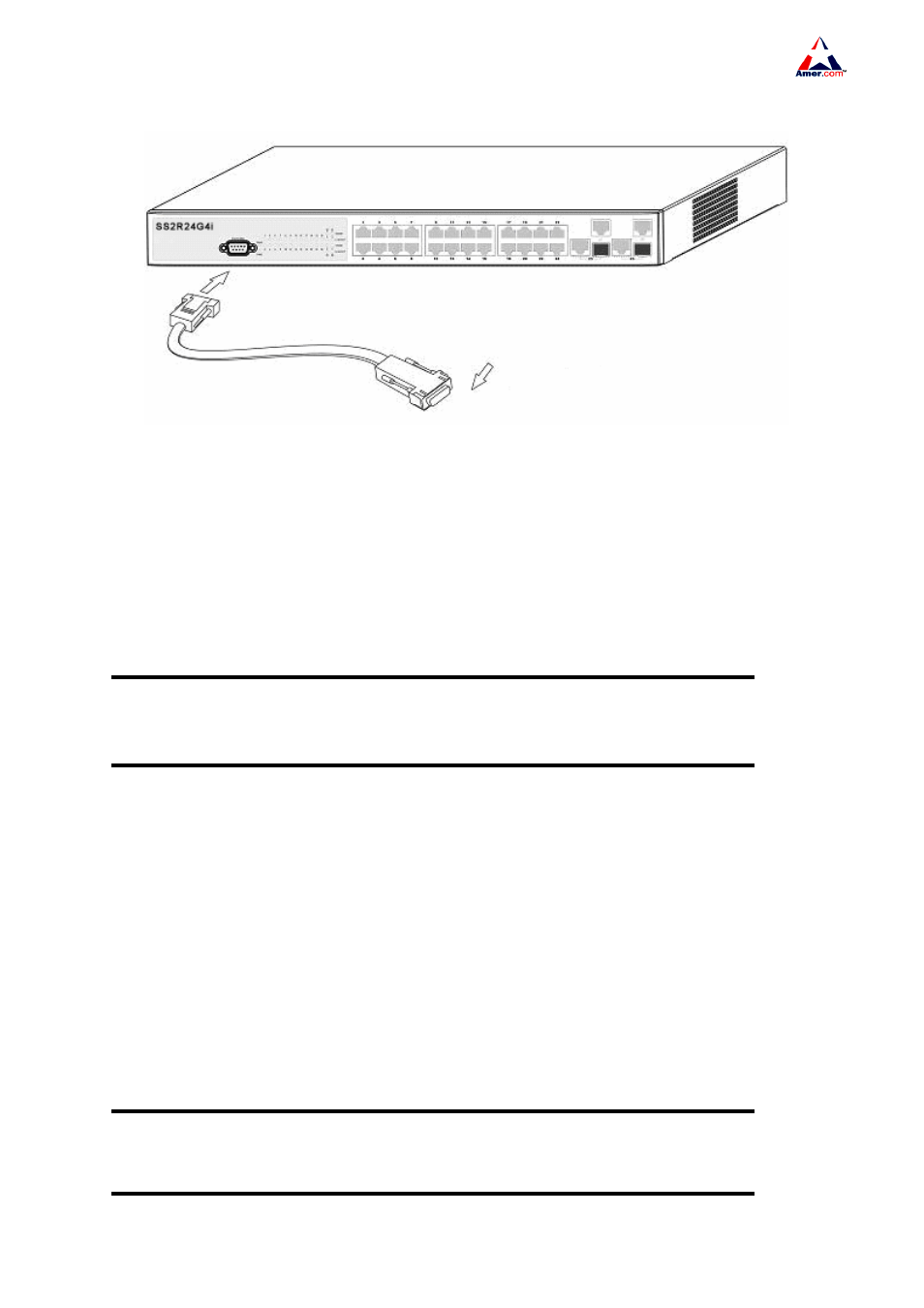
Fig 2-2 Connecting Console to SS2R24/48G4i switch
1. Find the console cable provided in the accessory kit. Attach the Mini-USB end to console port
of the switch.
2. Connect the other side of the console cable to a character terminal (PC).
3. Power on the switch and the character terminal. Configure the switch through the character
terminal.
Caution!
Please use the console cable and the console commutator of the switch.Don’t insert in error to
avoid break.
2.3.3 Power Supply Connection
SS2R24/48G4i switch uses 100 ~ 240VAC,50 ~ 60Hz supply by default. AC Power supply
connection procedure is described as below
1. Insert one end of the power cable provided in the accessory kit into the power source socket (with
overload and leakage protection), and the other end to the power socket in the back panel of the switch.
2. Check the power status indicator in the front panel of the switch. The corresponding power indicator
should light. SS2R24/48G4i switch is self-adjustable for the input voltage. As soon as the input voltage
is in the range printed on the switch surface, the switch can operate correctly.
3. When the switch is powered on, it executes self-test procedure and startups.
Caution!
The input voltage must be within the required range, otherwise the switch could malfunction of be
damaged. Do not open the switch shell without permission. It can cause physical injury