Altera JNEye User Manual
Page 129
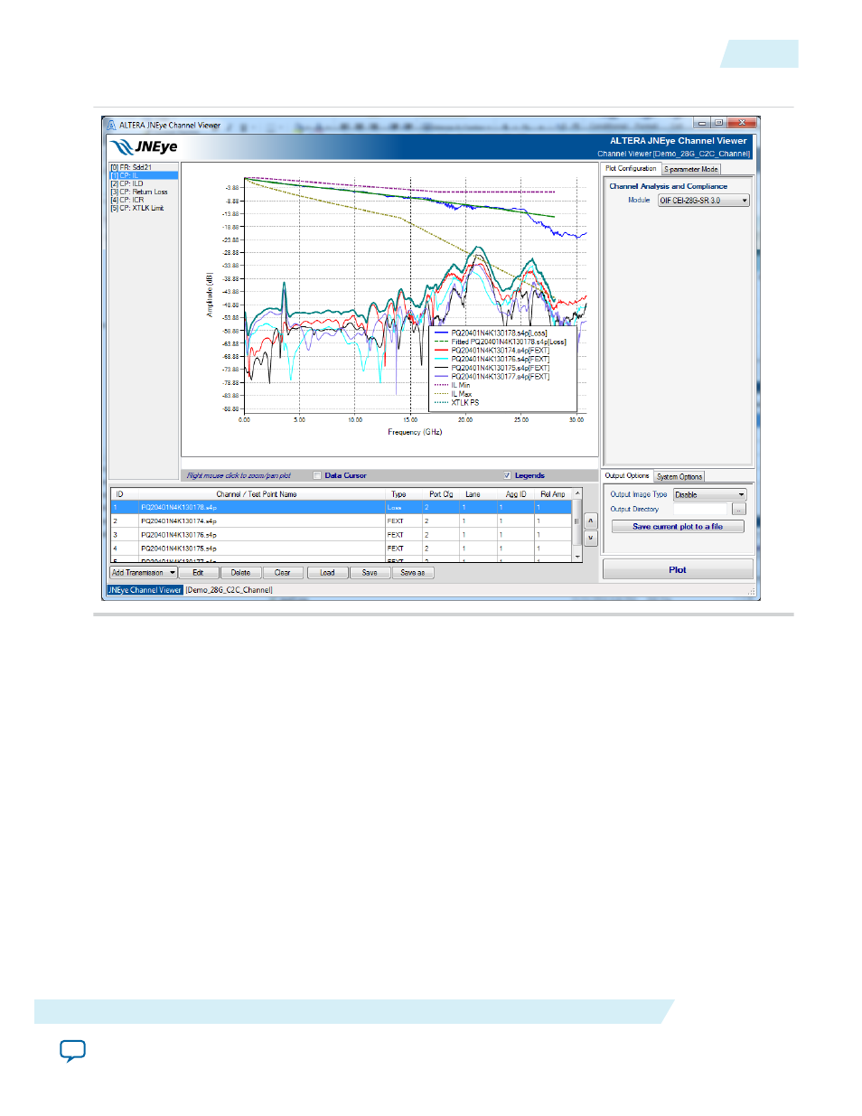
Figure 2-102: OIF CEI-28G-SR 3.0 Channel Compliance Check User Interface
OIF CEI-25G-LR, OIF CEI-28G-MR, and OIF-CEI-28G-SR channel compliances are similar in configura‐
tion and usage. Both cases are covered in this section. All parameters are predefined as described in the
OIF CEI-25G-LR, OIF CEI-28G-MR, and OIF-CEI-28G-SR standards, so there is no user input. Click
Plot to proceed. Channel Viewer computes and generates a sequence of plots that show the performance
of the channels in the channel list.
• Insertion Loss Plot—This plot is labeled CP: IL. In this plot, the insertion loss of channels, fitted curve
of transmission channels’ insertion loss, insertion loss masks, crosstalk channels’ amplitude, and power
sum of all crosstalk channels are shown. An example is illustrated in athe above figure.
• Insertion Loss Deviation Plot—This plot is labeled CP: ILD. In this plot, the insertion loss deviation
and ILD masks are shown, as in the following figure.
UG-1146
2015.05.04
Plot Configuration Panel
2-123
Functional Description
Altera Corporation