Altera JNEye User Manual
Page 8
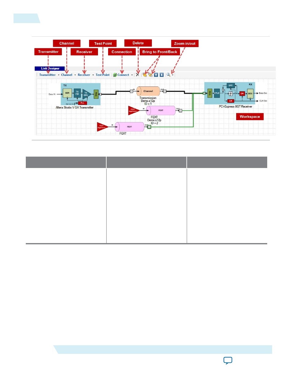
Figure 2-2: JNEye Link Designer Module
Table 2-1: Supported Transmitter, Channel, and Receiver Components
Transmitter (TX) Component
Channel Component
Receiver (RX) Component
Altera Stratix V GX
Altera Arria V GZ
Altera Stratix V GT
Altera Arria 10 GX/SX
Altera Arria 10 GT
IBIS-AMI
Custom
PCI-Express 8GT
Transmission
Connector
Far-end Crosstalk
Near-end Crosstalk
Package
AC Coupling Capacitor
Shunt Capacitor
Altera Stratix V GX
Altera Arria V GZ
Altera Stratix V GT
Altera Arria 10 GX/SX
Altera Arria 10 GT
IBIS-AMI
Custom
PCI-Express 8GT
JNEye supports the following simulations:
• Altera TX to Altera RX
• Altera TX to non-Altera RX
• Non-Altera TX to Altera RX
Note: Non-Altera to non-Altera link simulations are not supported.
A link consists of a transmitter, a receiver, and one or more channel components. Select the transmitter,
receiver, and channel components from the menus at the top of the Link Designer workspace.
After the link components are placed into the workspace, click Connect to connect the components. In
connect mode, one or two connectors are shown on each component. Connect the link components by
dragging the line from one connector to another. Two types of connections are provided in Link
Designer: Right Angled Line and Straight Line. Right Angled Line is the default connection method. Test
2-2
Constructing Communication Links in the Link Designer Module
UG-1146
2015.05.04
Altera Corporation
Functional Description