Altera JNEye User Manual
Page 143
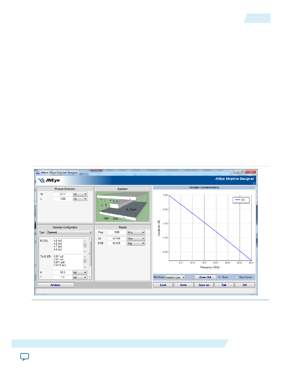
relative permittivity of the substrate determine the characteristic impedance of the strip which is a
transmission line. A typical stripline structure is shown in the following figure with these parameters:
• Input parameters
• W—Signal trace width (in various units)
• L—Signal trace length (in various units)
• T—Signal trace thickness (in various units)
• H—Separation between ground planes (in various units)
• Er (Dk)—Relative dielectric constant. JNEye Channel Designer supports frequency dependent
dielectric constant mapping.
• TanD (Df)—Dielectric loss tangent. JNEye Channel Designer supports frequency dependent
dissipation factor mapping.
• Cond—Conductor conductivity (S/m)
• Rough—Surface roughness (in various units)
• Mur—Relative permeability (no unit)
• Freq—Frequency where the Z0 (Impedance) and E-Eff (electrical length) are reported (in various
units)
• Output parameters
• Z0—Impedance at specified frequency Freq (Ohm)
• E-Eff—Electrical length (in various units)
Figure 2-113: Stripline Channel Component Configuration
The channel component designer GUI can perform parameter unit conversion interactively. For example,
you can change the length unit from mil to mm and the GUI will automatically compute the length value
with the new unit.
UG-1146
2015.05.04
JNEye Channel Designer
2-137
Functional Description
Altera Corporation