Altera JNEye User Manual
Page 169
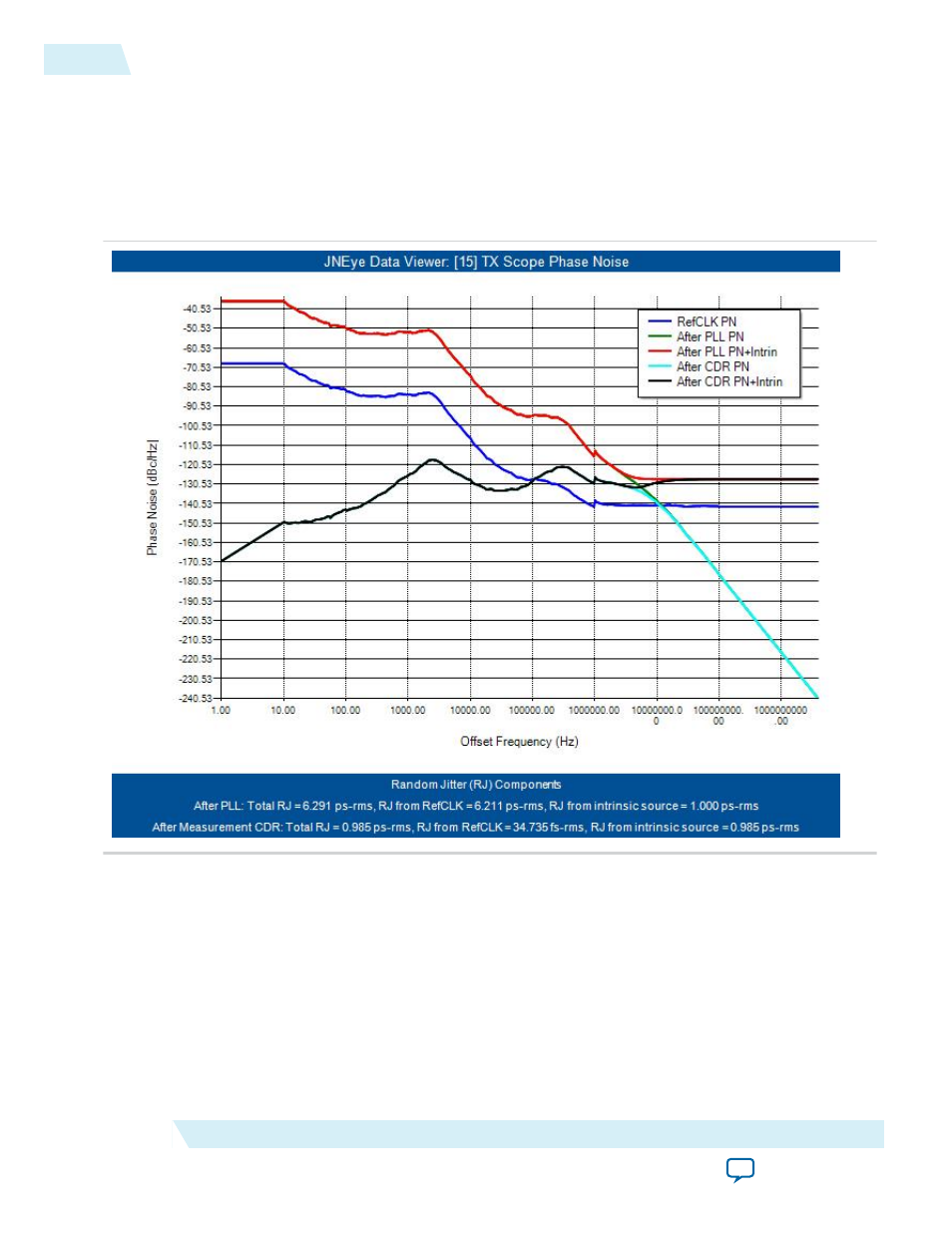
When you enable a PLL in a transmitter, the reference clock’s phase noise is shaped and filtered with the
PLL’s response. The following figure shows the characteristics of phase noise at the output of the reference
clock (blue), after the transmitter PLL (green), after the transmitter PLL plus the transmitter’s intrinsic
jitter (red), after the Golden CDR (most likely in a scope, cyan), and after the Golden CDR with
transmitter’s intrinsic jitter (black). The associated random jitter from the phase noise power spectrum at
each of the above stages are calculated and displayed in the text below the plot.
Figure 3-18: Reference Clock Phase Noise Characteristics Before and After TX PLL
At the channel output, which is located at the end of backplane channel with crosstalk, the eye diagram is
largely closed because of the large channel loss from the TX package and the backplane.
3-18
Analysis
UG-1146
2015.05.04
Altera Corporation
Tutorial: PCI Express 8GT