Altera JNEye User Manual
Page 190
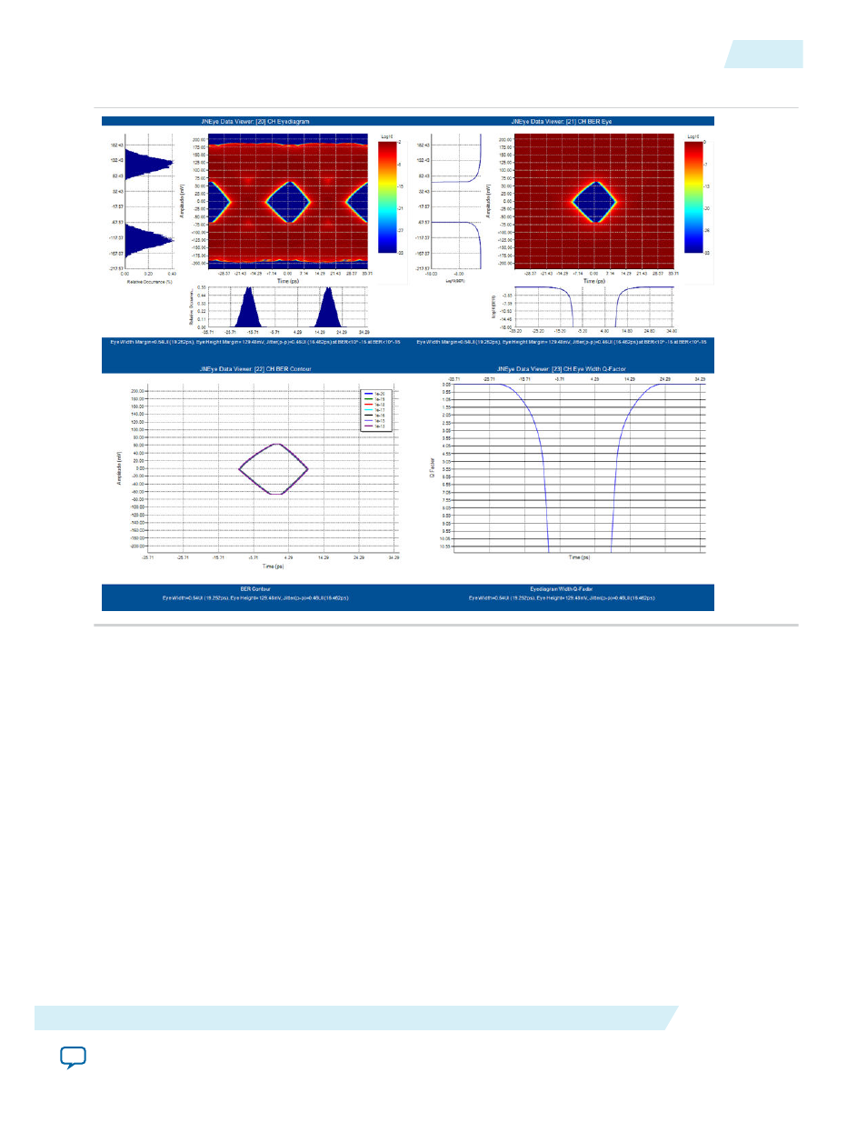
Figure 4-12: Channel Output Hybrid Eye Diagrams and BER Analysis
At the CTLE output, the signal after the receiver’s CTLE, the Arria 10 GT CTLE AC gain level 13 is
identified by JNEye’s link optimization algorithm as the optimal CTLE setting. Similar to the TX output
case, when the receiver CDR is enabled or included in the simulation, two sets of CTLE outputs are
shown. The first set of outputs is with the ideal clock and the second one is with the CDR recovered clock.
The total jitter is 0.69 UI (at BER < 10
–15
, with ideal clock) or 0.67 UI (with CDR recovered clock, if DFE
is not used). The eye diagram opening height margin is 83 mV (at BER < 10
–15
, with ideal clock) and 90
mV (with recovered clock). Because both the transmitter and receiver intrinsic jitter are included in the
simulation, the eye opening indicates the link margin at this observation point. Note that the eye opening
is smaller than the channel output results because the receiver intrinsic jitter is included in the CTLE
output results.
When you enable the CDR in a receiver, the transmitter random jitter is shaped and filtered with the
CDR’s response. Refer to the JNEye Tutorial: PCI Express 8GT for a demonstration of this part.
UG-1146
2015.05.04
Analysis
4-13
Tutorial: 28 Gbps OIF VSR Link with Arria 10 GT
Altera Corporation