Altera JNEye User Manual
Page 94
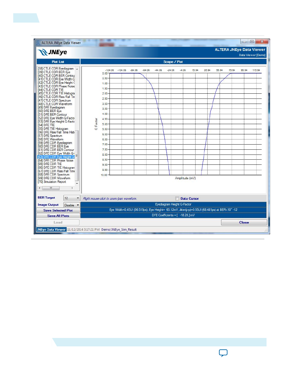
Figure 2-70: JNEye Data Viewer Q-Factor Plot (Amplitude Axis)
Transmitter Reference Clock Phase Noise Analysis and Plots
JNEye plots the phase noise power spectrum through the link. The transmitter reference clock’s phase
noise travels through the transmitter PLL, emulated scope, channel, and the RX CDR. In this process,
phase noise is shaped by the TX PLL, scope (pass through only), and RX CDR. At the same time, the
transmitter and receiver also generate their own intrinsic jitter which is mixed with the jitter caused by the
shaped phase noise. The JNEye simulation engine processes and records the phase noise characteristics
transition and the amount of random jitter the device contributed internally.
2-88
JNEye Data Viewer Module
UG-1146
2015.05.04
Altera Corporation
Functional Description