Transmitter options – Altera JNEye User Manual
Page 38
Note: Jitter specified in the Transmitter Noise/Jitter panel is the transmitter’s intrinsic jitter and noise.
Jitter specified in the Reference Clock configuration window is external reference clock jitter. You
must distinguish between these two parts and avoid double-counting jitter from the same source.
Transmitter Options
Transmitter options provide further configuration and setting options for transmitters. The additional
options are only displayed or valid for transmitter devices that allow custom configurations.
Note: Not all Transmitter Options are available for all transmitter devices.
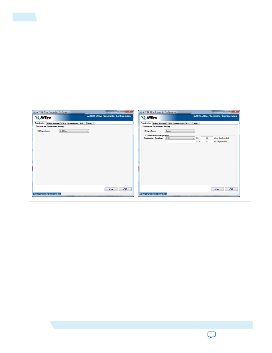
Termination tab
This section specifies the transmitter impedance.
Figure 2-22: Transmitter Advanced Options Window: Transmitter Termination
For selected Altera devices, use the TX Impedance pull-down menu to select a termination configuration.
You can also customize the termination configuration by selecting the Custom option. When the Custom
TX Impedance method is chosen, the termination can be configured as follows:
• Ideal TX termination—The transmitter is ideal with a 50 ohms (single-ended) termination.
• Non-ideal TX termination—Select one of the following options:
• R—Transmitter impedance is modeled as a resistance R ohms (single-ended).
• R//C1—Transmitter impedance is modeled as an RC network with a parallel resistor (in ohms) and
a capacitance (in pF).
• File Input (Frequency Real Imaginary)—Transmitter impedance is modeled by a frequency-
dependent complex impedance table described in the input file.
For an Altera transmitter, the default termination configurations are automatically selected and specified.
2-32
Transmitter Options
UG-1146
2015.05.04
Altera Corporation
Functional Description