Altera JNEye User Manual
Page 146
Coax Component
A coax transmission line consists of two round conductors in which one completely surrounds the other.
The two conductors are separated by a continuous solid dielectric. A typical coax structure is shown in the
following figure with these parameters:
• Input parameters
• a—Diameter of inner conductor (in various units)
• b—Diameter of outer conductor (in various units)
• t—Thickness of outer conductor (in various units)
• Length—Length of the coax (in various units)
• Er (Dk)—Relative dielectric constant. JNEye Channel Designer supports frequency dependent
dielectric constant mapping.
• TanD (Df)—Dielectric loss tangent. JNEye Channel Designer supports frequency dependent
dissipation factor mapping.
• Cond (a)—Conductor conductivity of inner conductor (S/m)
• Cond (b)—Conductor conductivity of outer conductor (S/m)
• Freq—Frequency where the Z0 (Impedance) and E-Eff (electrical length) are reported (in various
units)
• Output parameters
• Z0—Impedance at specified frequency Freq (Ohm)
• E-Eff—Electrical length (in various units)
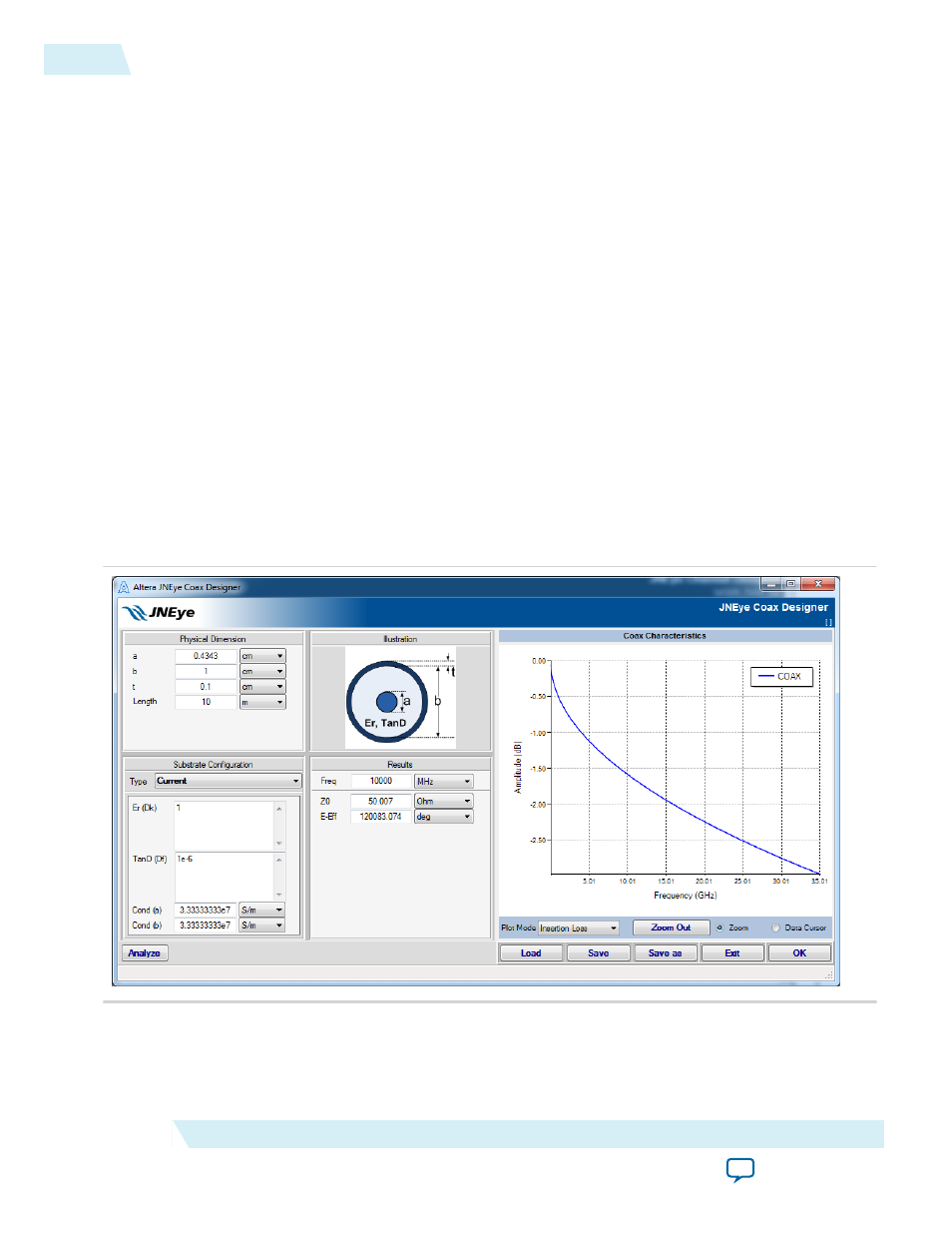
Figure 2-115: Coax Channel Component Configuration
The channel component designer GUI can perform parameter unit conversion interactively. For example,
you can change the length unit from mil to mm and the GUI will automatically compute the length value
with the new unit.
2-140
JNEye Channel Designer
UG-1146
2015.05.04
Altera Corporation
Functional Description