Altera JNEye User Manual
Page 62
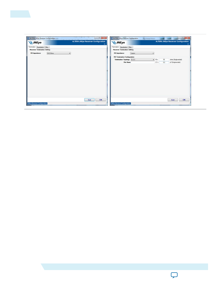
• Termination tab—This section specifies receiver impedance.
Figure 2-38: Receiver Termination Configuration
For selected Altera devices, use the RX Impedance pull-down menu to select a termination configura‐
tion. You can also customize the termination configuration by selecting the Custom option. When the
Custom RX Impedance method is chosen, the termination can be configured as follows:
• Ideal TX termination—The transmitter is ideal with a 50 ohms (single-ended) termination.
• Non-ideal TX termination—Select one of the following options:
• R—Transmitter impedance is modeled as a resistance R ohms (single-ended).
• R//C1—Transmitter impedance is modeled as an RC network with a parallel resistor (in ohms)
and a capacitance (in pF).
• File Input (Frequency Real Imaginary)—Transmitter impedance is modeled by a frequency-
dependent complex impedance table described in the input file.
For an Altera transmitter, the default termination configurations are automatically selected and
specified.
2-56
Receiver Options
UG-1146
2015.05.04
Altera Corporation
Functional Description