Altera JNEye User Manual
Page 20
Option 2 configures the reference clock with the following options:
• Phase Noise—Specify reference clock jitter using a phase noise profile. Reference clock phase noise is
specified with the noise power spectrum described with frequency and amplitude. The above figure
demonstrates a phase noise profile with a measured reference clock phase noise data set.
Note: Altera recommends that the maximum frequency range (f
MAX
) of the phase noise be set to the
reference clock frequency. If the f
MAX
is less than the reference clock frequency, JNEye uses
linear extrapolation to calculate the phase noise at f
MAX
, which can lead to inaccurate results.
• Spurs—Specify clock spectrum spurs with individual frequency (in Hz) and amplitude (in dBc). For
example, if the reference clock has three spurs: –80 dBc at 100 KHz, –90 dBc at 1 MHz, and –96 dBc at
10 MHz, you can input the following text into the text box:
100e3 -80
1e6 -90
10e6 -96
• Spur Phase Offset—Same as in Option 1 Reference Clock Jitter.
• Periodic Jitter Type—Same as in Option 1 Reference Clock Jitter.
• Plot / Update Plot—You can plot the input phase noise and spurs in the plotting area and confirm the
reference clock characteristics.
Link Optimization Method
JNEye can find optimal transmitter and receiver equalization settings with a user-specified link configura‐
tion.
Note: The TX/RX joint link optimization function is specific to JNEye and may not be supported by the
transmitter and receiver devices.
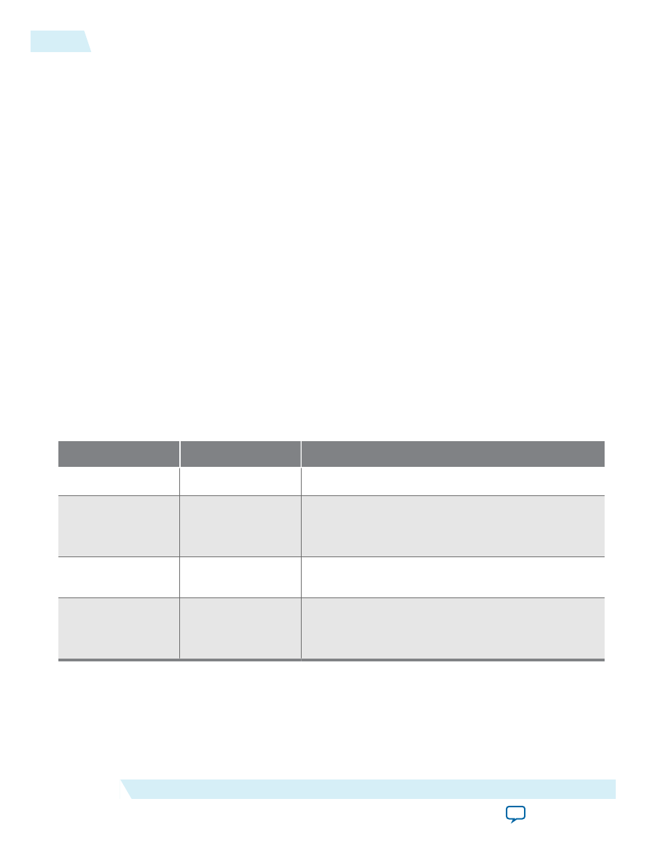
Table 2-4: Link Operation Modes Supported by JNEye
Transmitter Mode
Receiver Mode
Notes
Manual
Manual
Both TX and RX equalizations are manually set.
Auto /
Auto with Manual
Starting Point
Manual
JNEye finds optimal TX equalization setting. RX EQ
setting is manually set.
Manual
Auto
TX EQ is manually set. JNEye finds optimal RX EQ
setting.
Auto /
Auto with Manual
Starting Point
Auto
JNEye finds both TX and RX EQ settings.
JNEye has four link optimization methods for finding the optimal link setting, such as a transmitter pre-
emphasis and receiver CTLE and DFE with a given link configuration.
2-14
Link and Simulation Setting
UG-1146
2015.05.04
Altera Corporation
Functional Description