Altera JNEye User Manual
Page 9
points can be manually placed into the link by clicking Test Point and connecting to the desired location
in the link.
The following rules of link construction apply to the Link Designer module:
• A transmitter can only have one output port or connector
• A receiver can only have one input port or connector
• A channel component has one input and one output port
• A test point can only be connected to an input port
• A connection between two components can be established from an output port to an input port
• A transmitter cannot be connected directly to a receiver
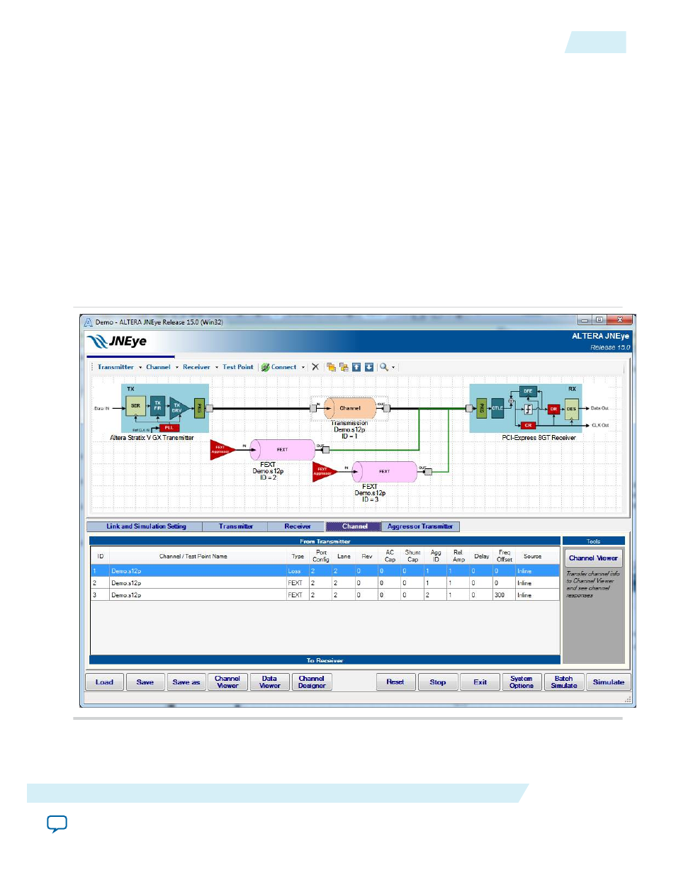
A link establishment checking algorithm runs constantly in the background, checking whether a link is
established for simulations. When a link is established between a transmitter and receiver, the link lines
become bold and color-coded. Bold black lines indicate signal paths, green lines indicate crosstalk signal
paths, and purple lines point to test point port locations. The following figure shows an example link
topology. A table of link components is displayed in the Channel tab for reference.
Figure 2-3: JNEye Link Designer with Channel Table
When a channel component (for example, a transmission line, connector, far-end crosstalk (FEXT), near-
end crosstalk (NEXT), package, AC coupling capacitor, or shunt capacitor) is chosen, the Channel
Wizard helps you verify or set the channel configuration.
UG-1146
2015.05.04
Constructing Communication Links in the Link Designer Module
2-3
Functional Description
Altera Corporation