L8 hardware protection, L8 hardware protection -48, Caution – Yaskawa P7 Drive User Manual User Manual
Page 132
Programming 5 - 48
L8 Hardware Protection
L8-02 Overheat Pre-Alarm Level
Setting Range:
50 to 130
o
C
Factory Default: 95
o
C
L8-03 Overheat Pre-Alarm Operation Selection
The Drive is capable of warning the operator of an impending heatsink over-temperature fault via an OH pre-alarm.The level at which the
pre-alarm will activate is determined by the setting of parameter L8-02. Measurement of the heatsink temperature is done with several
strategically mounted thermistors. If any of the heatsink thermistors measure a temperature in excess of the setting of L8-02, the Drive will
fault (OH2) and either: ramp to stop using the C1-02 deceleration rate (L8-03= “0: Ramp to Stop”), coast to stop (L8-03= “1: Coast to Stop”),
ramp to stop using the C1-09 fast stop deceleration rate (L8-03= “2: Fast-Stop”), alarm (OH) and continue running (L8-03 = “3: Alarm
Only”), alarm (OH) and continue running but at a reduced speed (L8-03= “4: Alarm & Reduce”). If L8-03= 4: Alarm and Reduce, the Drive
will continue to run but will reduce the speed to the level determined by parameter L8-19. Refer to the description for parameter L8-19.
If a digital output is configured for OH Prealarm (H2-01= “20: OH PreAlarm”), it will close whenever the heatsink tempera-
ture is greater than the L8-02 level no matter what the setting is of L8-03.
L8-06 Input Phase Loss Detection Level
Setting Range:
0.0 to 25.0% of Drives OV Trip point
Factory Default: KVA Dependent
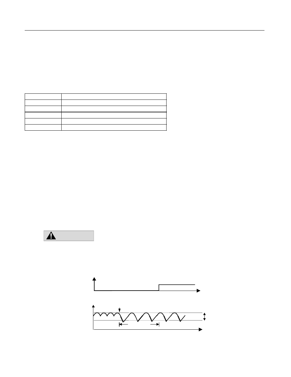
The Drive checks for a lost input phase by monitoring the DC Bus voltage ripple. After an initial delay of approximately 12 seconds, the Drive will
sample the DC BUS voltage every 1.28 seconds to determine the minimum and maximum voltage readings. The difference between the minimum
and maximum voltage is averaged over ten consecutive scans. If this “averaged” value is greater than the trip level as determined by L8-06 (L8-06 x
400 for 200 volt class Drives; L8-06 x 800 for 400 volt class Drives) the Drive shuts down and displays “PF”, an input phase loss fault.
Fig. 40 Input Phase Loss Detection Diagram
Setting
Description
0
Ramp to Stop (Decel Time C1-02)
1
Coast to Stop
2
Fast-Stop (Decel Time C1-09)
3
Alarm Only
4
OH Alarm and Reduce (factory default)
CAUTION:
Changing this parameter from the factory default setting may cause Drive failure
and void the product warranty. (Consult the factory for application assistance).
t
L8-06
Phase Loss
Fault Signal
DC Bus
Voltage
10 seconds
Fault Contact
t
Closed
Open
Input Phase Loss
Time