Alarm detection, Alarm detection -8, Diagnostic & troubleshooting 6 - 8 – Yaskawa P7 Drive User Manual User Manual
Page 152
Diagnostic & Troubleshooting 6 - 8
Alarm Detection
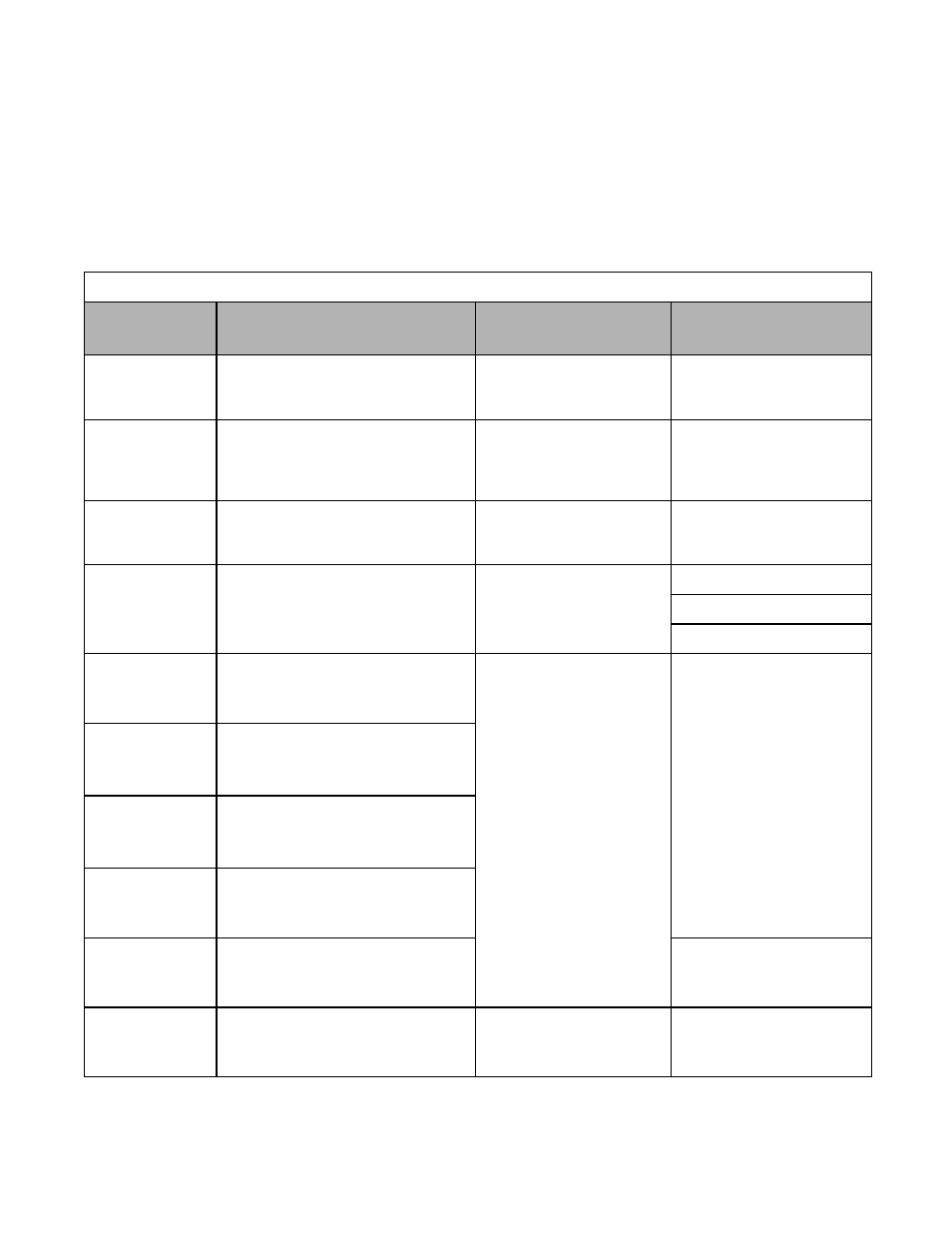
Table 6.2 Alarm Displays and Processing
Digital
Operator Display
Description
Cause
Corrective Action
BUS
Option Com Err
Option Communication Error
After initial communication was
established, the connection was lost.
Connection is broken, master
has stopped communicating
Check all connections, verify all
user side software configurations.
CALL
SI-F/G ComCall
Serial communication transmission error.
Communication has not yet been estab-
lished
Connection not made properly,
user software not configured to
the proper baud rate or
configuration
Check all connections, verify all
user side software configurations
EF
External Fault
Both the forward and the reverse run com-
mands are input simultaneously for 500mS
or more. This alarm stops the motor.
An external forward and
reverse command are input
simultaneously
Check external sequence logic
EF0
Opt External Flt
(Flashing)
Communication Option Card External Fault
An external fault condition
exists
Check for an external condition
Verify the parameters
Verify communication signal
EF3
Ext Fault S3
(Flashing)
External Fault at Terminal S3
An external fault condition
exists connected to a
multi-function digital input
Eliminate the cause of an external
fault condition
EF4
Ext Fault S4
(Flashing)
External Fault at Terminal S4
EF5
Ext Fault S5
(Flashing)
External Fault at Terminal S5
EF6
Ext Fault S6
(Flashing)
External Fault at Terminal S6
EF7
Ext Fault S7
(Flashing)
External Fault at Terminal S7
Remove the fault from a multi-
function digital input
DNE
Drive not Enable
(Flashing)
The Drive does not have the enable com-
mand when the run command is applied
The Run command has been
applied prior to the enable signal
Apply the enable command
before applying the run command
Alarms are Drive protection functions that does not operate the fault contact. The Drive will automatically return to its original
status once the cause of the alarm has been removed.
During an alarm condition, the Digital Operator display flashes and an alarm output is generated at the multi-function outputs
(H2-01 to H2-02) if programmed.
When an alarm occurs, take appropriate corrective action according to the table below.