Main circuit terminal functions, Electrical installation 2 - 8 – Yaskawa P7 Drive User Manual User Manual
Page 36
Advertising
Electrical Installation 2 - 8
Main Circuit Terminal Functions
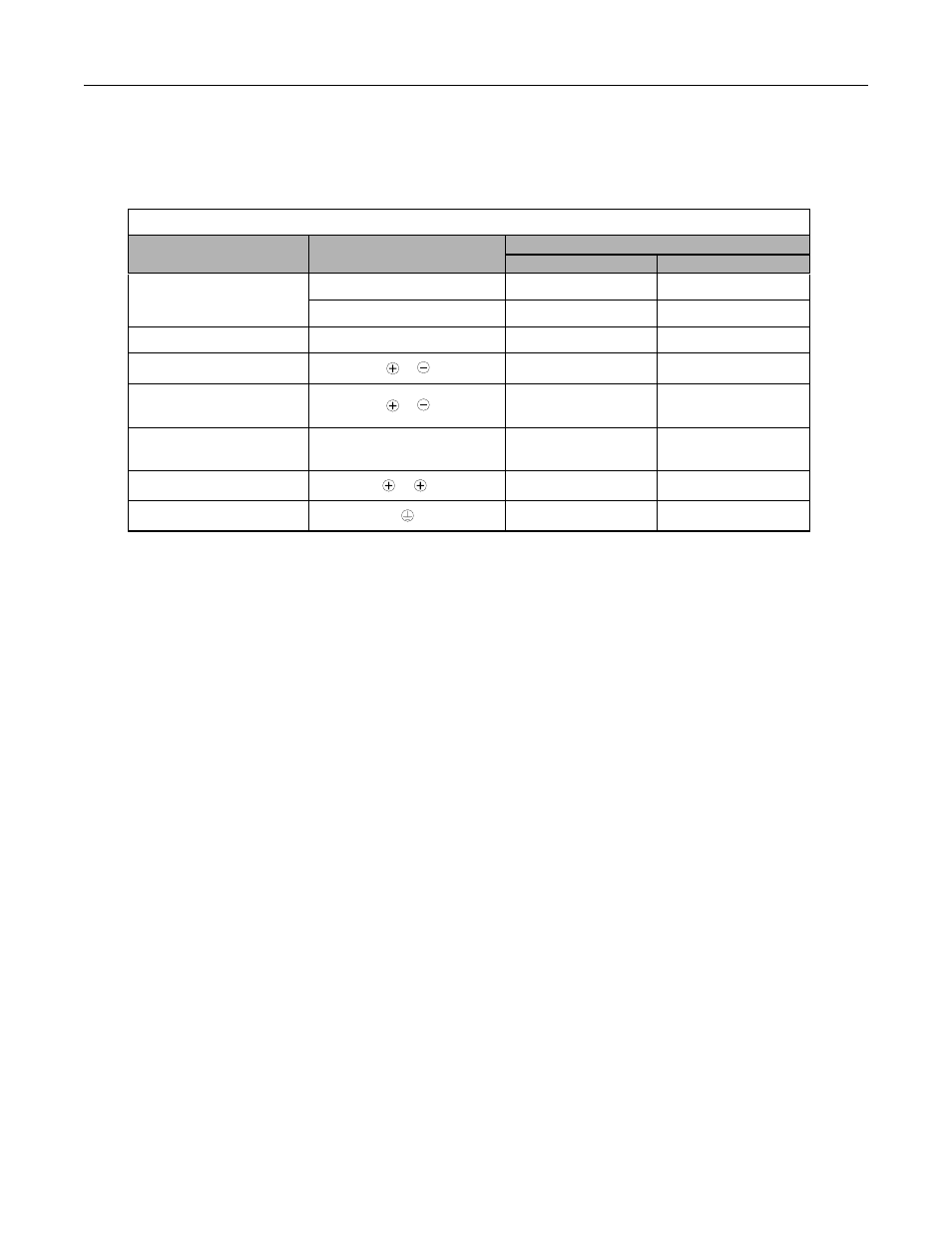
Main circuit terminal functions are summarized according to terminal symbols in Table 2.3. Wire the terminals correctly for
the desired purpose.
Table 2.3 Main Circuit Terminal Functions (208-240Vac and 480Vac)
Purpose
Terminal Designation
Model: CIMR-P7U
_ _ _ _
208-240Vac
480Vac
Main circuit power input
R/L1, S/L2, T/L3
20P4 to 2110
40P4 to 4300
R1/L11, S1/L21, T1/L31
2022 to 2110
4030 to 4300
Drive outputs
U/T1, V/T2, W/T3
20P4 to 2110
40P4 to 4300
DC power input
1,
20P4 to 2110
40P4 to 4300
Braking Transistor
Unit Connection
3,
2022 to 2110
4030 to 4300
Braking Resistor
Unit Connection
B1, B2
20P4 to 2018
40P4 to 4018
DC reactor connection
1, 2
20P4 to 2018
40P4 to 4018
Ground
20P4 to 2110
40P4 to 4300
Advertising