Diagnostic & troubleshooting 6 - 9 – Yaskawa P7 Drive User Manual User Manual
Page 153
Diagnostic & Troubleshooting 6 - 9
FAN
Cooling Fan Error
Failure of the Drive internal cooling fan
when L8-32=0
Drive cooling fan has stopped
Replace the cooling fan
FBL
Feedback Loss
PI Feedback Loss
This fault occurs when PI Feedback Loss
Detection is programmed to fault
(b5-12 = 2) and the
PI Feedback < PI Feedback Loss Detection
Level (b5-13) for the PI Feedback Loss
Detection Time (b5-14)
PI Feedback source
(e.g. transducer, sensor, build-
ing automation signal) is not
installed correctly or is not
working
Verify Drive is programmed to
receive the PI Feedback source
signal
Check to ensure the PI Feedback
source is installed and working
properly
Check the motor for a phase-to-
phase short
Check the Drive for a phase-to-
phase short at the output
Verify C1-01 and C1-02 are set
correctly
Check load conditions
LL3
Loss of Load Det 1
(Flashing)
Loss of Load Detection 1
Drive output current < L6-02 for more than
the time set in L6-03
Motor is underloaded
Ensure the values in
L6-02 and L6-03 are appropriate
Check application/machine status
to eliminate fault
OH
Heatsnk Overtemp
(Flashing)
Cooling Fin/Cooling Fin Fan Overheat
The temperature of the Drive cooling fin
exceeded the temperature programmed in
parameter L8-02
Cooling fan(s) are not working,
high ambient temperature, a
heating unit in close proximity
to Drive is present
Check for dirt build-up on the
fans and cooling fins
Reduce the ambient temperature
around the Drive
Drive Internal Cooling Fan
Remove the heating unit
OH2
Over Heat 2
(Flashing)
Drive overheat pre-alarm signal is input
from a multi-function digital input terminal
An external overheat condition
exists connected to one of the
multi-function input terminals
S3, S4, S5, S6 or S7
Check for an external condition
Verify the program parameters
H1-01 thru H1-05
OH3
Motor Overheat 1
(Flashing)
Motor Overheating Alarm
The Drive stops or continues operation
according to the setting of L1-03.
Overheating of motor
Recheck the cycle time and the
size of the load
Recheck the accel/decel time
(C1-01 and C1-02)
Recheck the V/F pattern (E1-01
thru E1-13)
Recheck the motor rated current
value (E2-01)
Check the digital operator
connector
Verify the setting of
o2-06
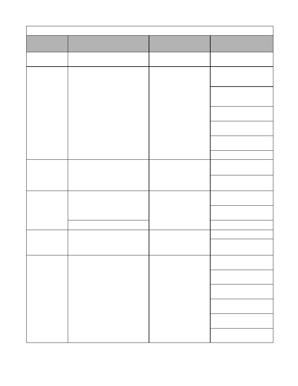
Table 6.2 Alarm Displays and Processing
Digital
Operator Display
Description
Cause
Corrective Action