B5 pi function, B5 pi function -15, Programming 5 - 15 – Yaskawa P7 Drive User Manual User Manual
Page 99: Fig. 15 pi block diagram
Programming 5 - 15
b5 PI Function
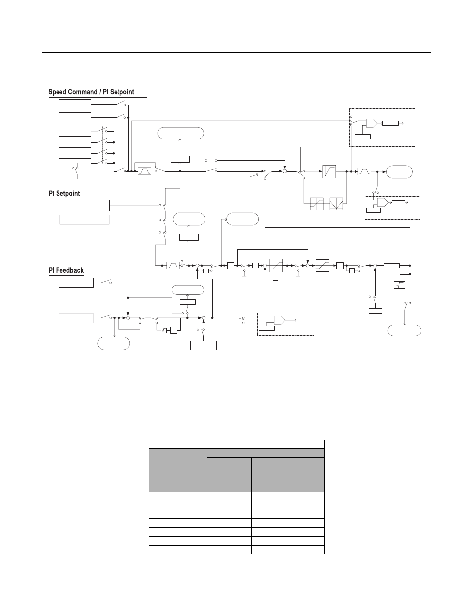
The capability to accept an analog signal as feedback for a PI (Proportional + Integral) control function is built into the Drive.
Fig. 15 PI Block Diagram
The analog feedback to the Drive for the PI control is via the A2 terminal. The Drive must be programmed (H3-09= “B: PI
Feedback”) to use terminal A2 as feedback for the PI functionality of the Drive.
The PI setpoint can be configured to come from one of many different inputs or parameters. The table below describes the
options for originating the PI setpoint.
Table 1 PI Setpoint Options
The PI Setpoint
will be read from:
If these conditions are true
Status of
b5-18
Status of
Modbus
Register
0Fh bit 1
Status of
b1-01
Parameter b5-19
= 1
N/A
N/A
Modbus Register
06H
= 0
ON
N/A
D1-01
= 0
OFF
= 0
Terminal A1
= 0
OFF
= 1
Serial Comm.
= 0
OFF
= 2
Option PCB
= 0
OFF
= 3
Option Card
Serial Com
Terminal A1
D1-01
D1-04
D1-02
Output
frequency
P
1/t
1/t
Z
-1
b1-01
1
2
3
Frequency Reference
using multi-step
command
Frequency reference
(U1-01)
PI Set Point
(U1-38)
Proportional
gain
b5-02
I-time
b5-03
I - limit
b5-04
PI Limit
b5-06
PI delay time
b5-08
PI offset
(b5-07)
+
+
+ +
PI output monitor
(U1-37)
b5-01=0
ON
PI control is OFF under the following
conditions:
- b5-01=0
- During JOG command input
- H3-xx=19 and the terminal status is
ON
Upper limit
Fmax x109%
+
+
b5-01=3
b5-01=1
Upper limit
Fmax x109%
Lower limit
Fmax x109%
Lower limit 0
4
MEMOBUS Reg. 06H
PI target value
Integral Hold
H1-xx=31
Integral Reset
H1-xx=30
PI Output
Characteristic
b5-09
b5-11
1
0
Enable / Disable reverse operation
when PI output is negative
Constant b5-19
b5-18
0
1
0
PI SFS
b5-17
PI SFS cancel
H1-xx=34
0
1
o1-03
Scaling
b5-20
Scaling
1
0
1
1
0
Reg. 0Fh, bit 1
Terminal A1
Terminal A2
PI Differential
Fdbk. H3-09=16
1
0
H3-09=B
1
0
1
0
PI Differential
Fdbk. H3-09=16
PI Differential
Fdbk. H3-09=16
Z
-1
1
0
1
0
PI Input
Caracteristic
H1-xx=35
1
0
Z
-1
PI SFS
b5-17
PI SFS cancel
H1-xx=34
0
1
b5-20
Scaling
PI Input
(U1-36)
+
-
PI Feedback 2
(U1-53)
0
1
PI Differential
Fdbk. H3-09=16
1
0
b5-28
PI Feedback
(U1-24)
b5-20
Scaling
1
0
1
0
b5-07
0
1
+
+
PI Differential
Fdbk. H3-09=16
-
+
+
+
+
-
b5-24
PI Wake Up Level
PI
Wake Up
PI Snooze Function
b5-10
0
1
b5-30
PI Output
Gain
PI offset
H3-09=16
+
-
b5-22
PI Snooze Level
PI
Snooze
PI Snooze Function
+
-
b5-15
Sleep Level
RUN
on/off
0
1
b5-16
Delay
Timer
Sleep Function
Sleep function
selection b5-21
SFS
OFF
b5-23
Delay
Timer
PI Differential
Fdbk. H3-09=16
2
2
0
o
r 1
0 or 1
2
Sleep function
selection b5-21
Sleep function
selection b5-21
P
b5-29
Characteristic
H1