Yaskawa P7 Drive User Manual User Manual
Page 82
Start Up 4 - 8
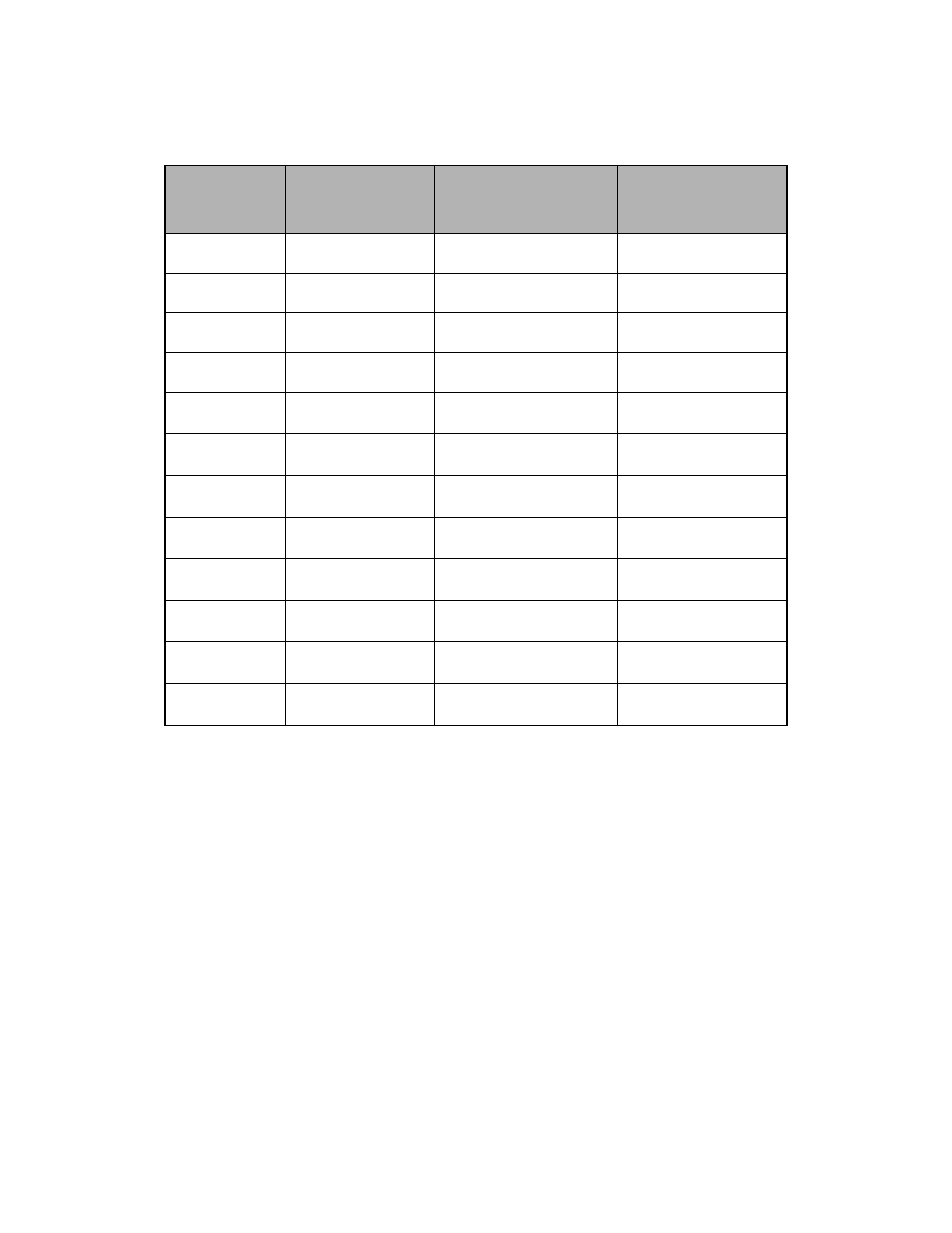
18. Press the MONITOR key to display the U1 monitors. Use the S and T keys to view Output Current (U1-03),
Output Voltage (U1-06), and DC Bus Voltage (U1-07) while running the Drive throughout its entire speed range.
Record the following information at each speed:
When this table is complete, press the STOP key. The Drive will stop and the FWD light remains on. This step
provides benchmark data for the application from the initial start up.
19. Press the MENU key once to display “Operation”. Press the DATA/ENTER key to display “Frequency Ref”.
If using a remote speed command, press the LOCAL/REMOTE key so the REMOTE SEQ and REMOTE REF
indicators are on. This puts the Drive in Remote mode.
20. If using an external speed command, determine whether the speed command is a 0-10Vdc or a 4-20mA signal.
Connect the positive side of a 0-10Vdc signal to terminal A1. Connect the positive side of a 4-20mA signal to ter-
minal A2. Connect the COMMON of the speed command to terminal AC.
Note: Connect only one input. The factory default is 0-10Vdc. To change to 4-20mA adjust parameter H3-08
to “2:4 – 20mA” and ensure DIP Switch S1-2 (located on the terminal board) is in the ON position.
Frequency
(Hz)
Monitor U1-01
Output Current
(A)
Monitor U1-03
Output Voltage
(VAC)
Monitor U1-06
DC Bus Voltage
(VDC)
Monitor U1-07
6.0
10.0
15.0
20.0
25.0
30.0
35.0
40.0
45.0
50.0
55.0
60.0