Yaskawa Sigma-5 User Manual: MECHATROLINK-II Commands User Manual
Page 103
5 Command Related Parameters
5.2.4 Command Data Options
5-14
Note: 1. Do not allocate more than one signal to one bit. If more than one signal is allocated to one bit, the bit will control
more than one signal.
2. An unallocated function bit acts as if it is set to 0.
3. Set the bit to the least significant bit position to be allocated.
4. To enable the OUT_SIGNAL function, set the following parameters to ZERO: Pn50E, Pn50F, and Pn510.
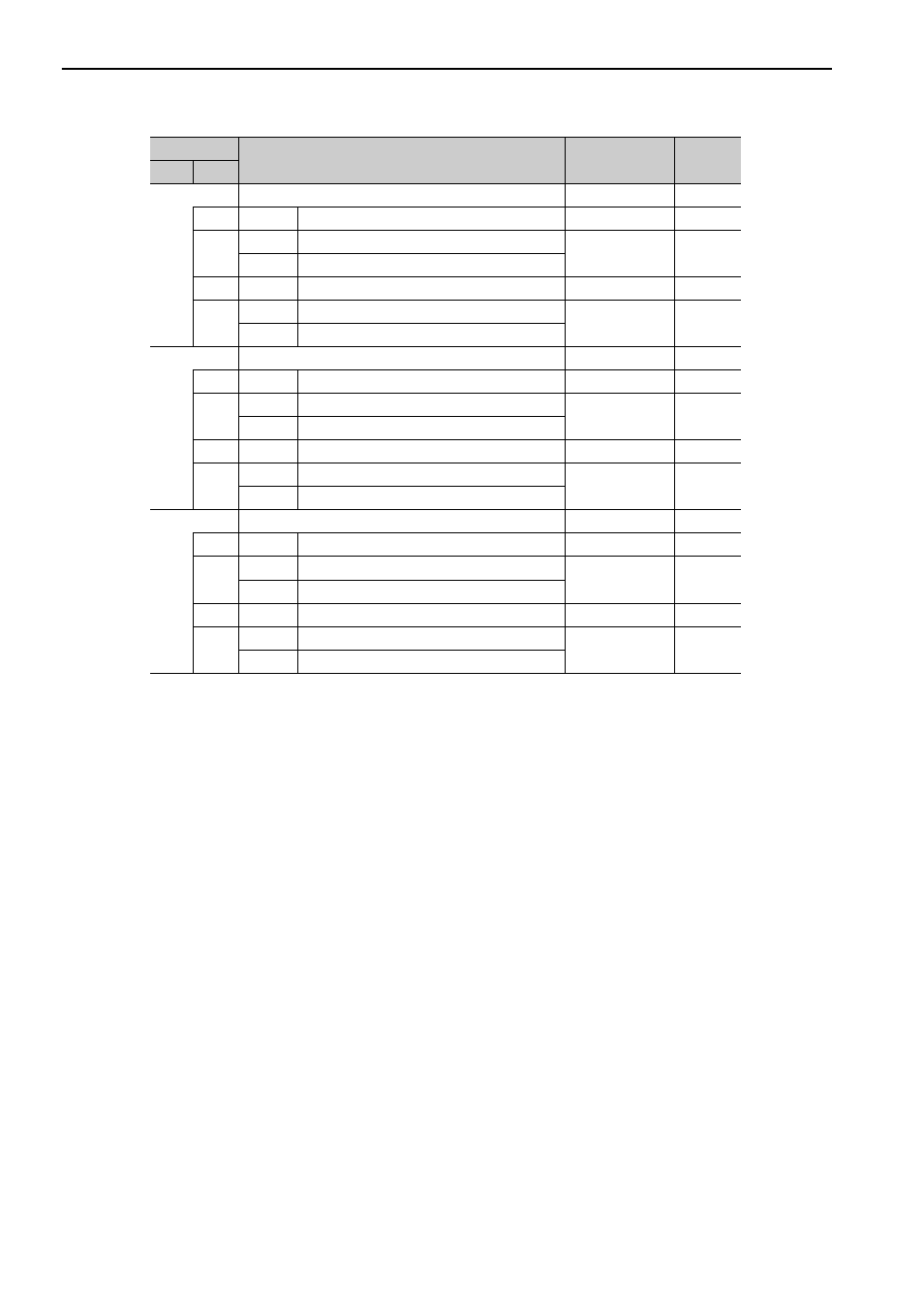
Pn82C
OPTION Field Allocation 3
0000H to 1F1FH
1F1EH
0
0 to F
P_CL bit position
E
1
0
Disables P_CL bit allocation.
1
1
Enables P_CL bit allocation.
2
0 to F
N_CL bit position
F
3
0
Disables N_CL bit allocation.
1
1
Enables N_CL bit allocation.
Pn82D
OPTION Field Allocation 4
0000H to 1F1CH
0000H
0
0 to C
BANK_SEL1 bit position
0
1
0
Disables BANK_SEL1 bit allocation.
0
1
Enables BANK_SEL1 bit allocation.
2
0 to F
LT_DISABLE bit position
0
3
0
Disables LT_DISABLE bit allocation.
0
1
Enables LT_DISABLE bit allocation.
Pn82E
OPTION Field Allocation 5
0000H to 1D1FH
0000H
0
0 to F
Reserved
0
1
0
Reserved
0
1
Reserved
2
0 to D
OUT_SIGNAL bit position
0
3
0
Disables OUT_SIGNAL bit allocation.
0
1
Enables OUT_SIGNAL bit allocation.
Parameter
Name
Setting Range
Factory
Setting
No.
Digit