1 preparing for operation, 1 setting mechatrolink-ii communications, 1 preparing for operation -2 – Yaskawa Sigma-5 User Manual: MECHATROLINK-II Commands User Manual
Page 19: 1 setting mechatrolink-ii, 1 setting mechatrolink-ii communications -2, Setting the communications specifications
2 Operation Sequence
2.1.1 Setting MECHATROLINK-II Communications
2-2
2.1 Preparing for Operation
This section describes how to set communications specifications before starting communications, and how to
confirm the communications status.
2.1.1 Setting MECHATROLINK-II Communications
(1) When the
Σ-V Series SERVOPACKs (SGDV-A11, -A15, -D11,
-D15, -F11, -F15) are Used
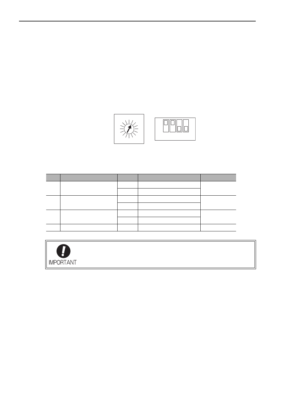
The rotary switch (SW1) and DIP switch (SW2), which are located near the top under the front cover of the
SERVOPACK, are used as shown below to set the MECHATROLINK-II communications specifications.
Setting the Communications Specifications
Set the communications specifications using the DIP switch (SW2).
ON
OFF
SW2 (factory settings)
SW1 (factory setting)
1
2
3
4
0
F
1
E
2
D
3
8
4
C
B
5
A
6
9
7
SW2
Function
Setting
Description
Factory setting
Pin 1 Sets the baud rate.
OFF
4 Mbps (MECHATROLINK-I)
ON
ON
10 Mbps (MECHATROLINK-II)
Pin 2 Sets the number of
transmission bytes.
OFF
17 bytes
ON
ON
32 bytes
Pin 3 Sets the station address.
OFF
Station address = 40H + SW1
OFF
ON
Station address = 50H + SW1
Pin 4 Reserved. (Do not change.)
OFF
–
OFF
• When connecting to a MECHATROLINK-I network, turn OFF pins 1 and 2.
• When using a MECHATROLINK-I network (Baud rate: 4 Mbps), the settings for the
number of transmission bytes is disabled and the number of transmission bytes is
always 17.