5 position data latch function setting, 1) latching allowable area, 2) continuous latch function – Yaskawa Sigma-5 User Manual: MECHATROLINK-II Commands User Manual
Page 104: 5 position data latch function setting -15
5.2 Command Related Parameters Details
5-15
5
Command Related Parameters
5.2.5 Position Data Latch Function Setting
This section describes the parameters for setting the position data latch function.
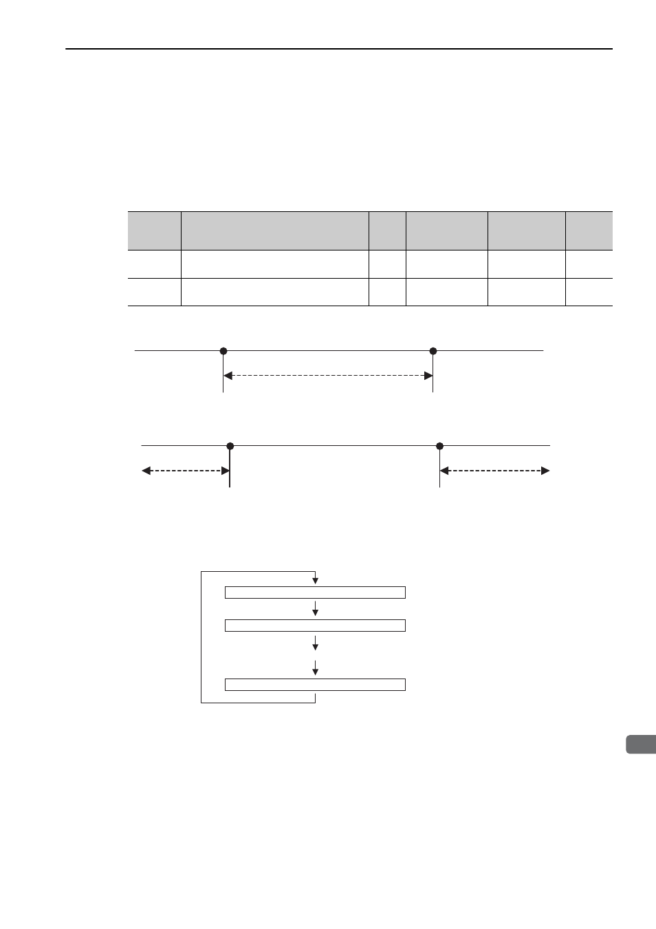
(1) Latching Allowable Area
Use the following parameters to set the range to input the latch signal for position data latching by
LTMOD_ON, LATCH, EX_POSING, or ZRET command. If the latch signal is input out of the set range, posi-
tion data will not be latched.
When Pn820 > Pn822
When Pn820
≤ Pn822
(2) Continuous Latch Function
This function sequentially latches the input positions of sequence signal 1 to sequence signal n (n = 1 to 8) for
a specified number of times. The continuous latch operation can be aborted by executing the LTMOD_OFF
command. This function can shorten the time between latch completion and the start of the next latch, and
enables sequential latch operations at high speed.
Parameter
No.
Name
Data
Size
(byte)
Setting Range
Unit
Factory
Setting
Pn820
Forward Latching Allowable Area
4
–2147483648 to
2147483647
Reference unit
0
Pn822
Reverse Latching Allowable Area
4
–2147483648 to
2147483647
Reference unit
0
Pn822
Pn820
Latching allowable area
Pn820
Pn822
Latching allowable area
Latching allowable area
Latches the sequence signal 1 input position.
Latches the sequence signal 2 input position.
Repeats m times
Latches the sequence signal n input position.
..
Note 1: N, the number of sequence signals,
is specified by Pn850.
2: The signals for sequence signal n
are selected by Pn852 and Pn853.
3: The number of times of continuous
latching m is set by Pn851.