Yaskawa Sigma-5 User Manual: MECHATROLINK-II Commands User Manual
Page 108
5.2 Command Related Parameters Details
5-19
5
Command Related Parameters
[Setting Procedure]
STEP 1:
1. Set Pn900 (Parameter Bank Number) to m.
2. Set Pn901 (Parameter Bank Member Number) to n.
Set Pn900 and Pn901 so that Pn900 × Pn901
≤ 64.
3. Register bank member parameter numbers using parameters Pn902 to Pn910.
4. To enable the bank function, execute the CONFIG command or turn the power supply OFF and then ON
again.
STEP 2:
5. Set the data of each bank in the parameter bank data area from the leading parameter Pn920 in order as
shown below.
Bank 0: Pn920 to Pn (920+n-1)
Bank 1: Pn (920+n) to Pn (920+2n-1)
…
Bank m-1: Pn {920+(m-1)×n} to Pn (920+m×n-1)
Note: 1. If parameters Pn900 to Pn910 set in STEP 1.1, 1.2, and 1.3 are saved in the non-volatile memory, carry out STEP
2.5 only after power up.
However, if you turn the power supply OFF and then ON again after saving parameters Pn900 to Pn910 in the
non-volatile memory, and start the operation without setting parameters Pn920 to Pn95F, the operation will be
carried out under the condition that all bank data is set to 0 (zero) or the minimum setting.
2. If parameters Pn900 to Pn910 set in STEP 1.1, 1.2, and 1.3 are not saved in the non-volatile memory, carry out
STEP 1.1 to 2.5 each time the power supply is turned ON.
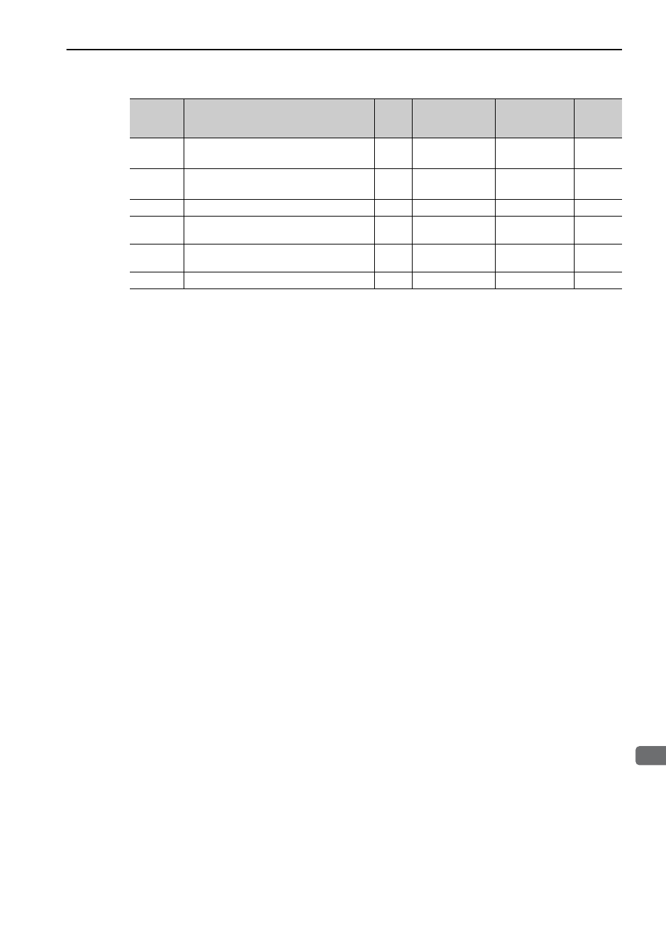
Pn83A
1st Linear Deceleration Constant 2
4
1 to 20971520
10000
reference units/s
2
100
Pn83C
2nd Linear Deceleration Constant 2
4
1 to 20971520
10000
reference units/s
2
100
Pn83E
Deceleration Constant Switching Speed 2
4
0 to 2097152000
Reference unit/s
0
Pn810
Exponential Function Acceleration/Decelera-
tion Bias
2
0 to 65535
100 reference
units/s
0
Pn811
Exponential Function Acceleration/Decelera-
tion Time Constant
2
0 to 5100
0.1 ms
0
Pn812
Movement Average Time
2
0 to 5100
0.1 ms
0
Parameter
No.
Name
Data
Size
(byte)
Setting Range
Unit
Factory
Setting