1 main command data field, 1 status field specifications, 1 main command data field -2 – Yaskawa Sigma-5 User Manual: MECHATROLINK-II Commands User Manual
Page 121: 1 status field specifications -2
7 Data Field
7.1.1 Status Field Specifications
7-2
7.1 Main Command Data Field
The data of each field in the main commands or subcommands is described below.
7.1.1 Status Field Specifications
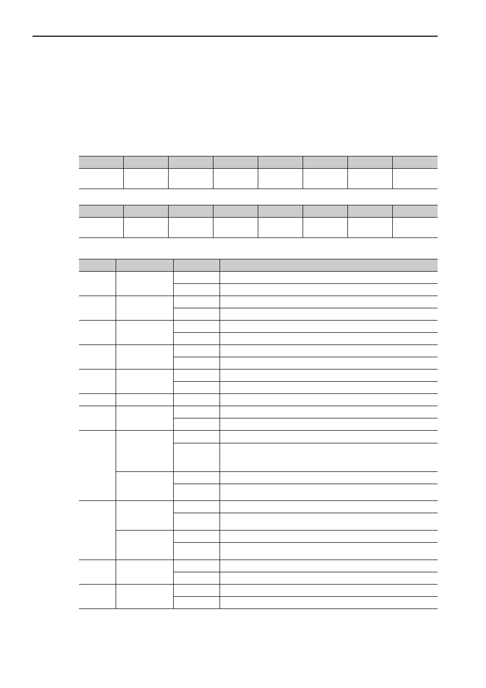
The status field is used to monitor the SERVOPACK status.
The following table shows the bit allocation in the status field.
The following table explains each bit value and its status.
D7
D6
D5
D4
D3
D2
D1
D0
PSET/
V_CMP
ZPOINT
–
PON
SVON
CMDRDY
WARNG
ALM
D15
D14
D13
D12
D11
D10
D9
D8
–
–
N_SOT
P_SOT
NEAR/
V_LIM
L_CMP
T_LIM
DEN/ZSPD
Bit
Name
Value
Description
D0
ALM
0
No alarm
1
Alarm occurs.
D1
WARNG
0
No warning
1
Warning occurs.
D2
CMDRDY
0
Command cannot be received (busy).
1
Command can be received (ready).
D3
SVON
0
Servo OFF
1
Servo ON
D4
PON
0
Main power supply OFF
1
Main power supply ON
D5
–
–
–
D6
ZPOINT
0
Out of home position range
1
Within home position range
D7
PSET
(During position
control)
0
Out of positioning complete range
1
Within positioning complete range
(The output is completed (DEN = 1) and APOS is within the positioning
complete range.)
V_CMP
(During speed
control)
0
Speed does not coincide.
1
Speed coincides.
D8
DEN
(During position
control)
0
During output
1
Output completed
ZSPD
(During speed
control)
0
Zero speed not detected
1
Zero speed detected
D9
T_LIM
0
Not during torque (force) limit
1
During torque (force) limit
D10
L_CMP
0
Latch not completed
1
Latch completed