Base addresses, Base addresses –4 – Altera 10-Gbps Ethernet MAC MegaCore Function User Manual
Page 22
3–4
Chapter 3: 10GbE MAC Design Examples
10GbE Design Example Components
10-Gbps Ethernet MAC MegaCore Function User Guide
February 2014
Altera Corporation
■
Line loopback—turn on this loopback to verify the functionality of the PHY when
verifying the design example in hardware. When you enable the line loopback, the
Ethernet loopback module takes the XGMII RX signal received from the PHY and
loops it back to the PHY’s XGMII TX signal. During this cycle, the loopback
module also forwards the XGMII RX signal to the MAC. While the line loopback is
turned on, the loopback module ignores any frame transmitted from the MAC.
describes the registers you can use to enable or disable the desired loopback.
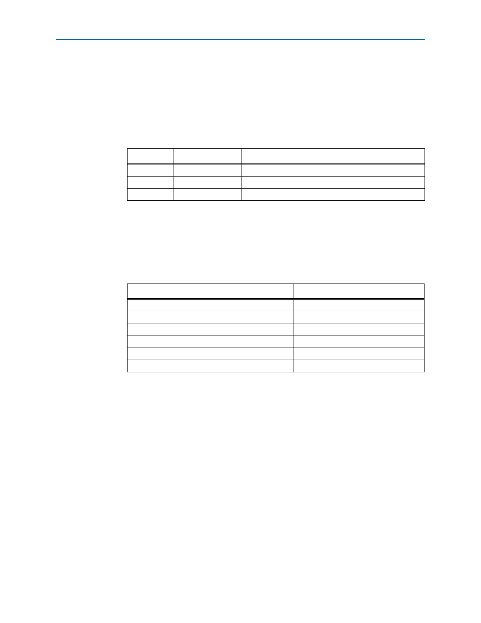
3.2.0.2. Base Addresses
Table 3–2
lists the design example components that you can reconfigure to suit your
verification objectives. To reconfigure the components, write to their registers using
the base addresses listed in the table and the register offsets described in the
components' user guides. Refer to
for the Ethernet loopback registers.
1
This design example uses a 19-bit width address bus to access the base address of
components other than the MAC.
Table 3–1. Loopback Registers
Byte Offset
Register
Description
0x00
line loopback
Set this register to 1 to enable line loopback; 0 to disable it.
0x04
Reserved
—
0x08
local loopback
Set this register to 1 to enable local loopback; 0 to disable it.
Table 3–2. Base Addresses of Design Example Components
Component
Base Address
10GbE MAC
0x000
XAUI or 10GBASE-R PHY
0x40000
MDIO
0X10000
Ethernet loopback
0x10200
RX FIFO (Avalon-ST Single-Clock FIFO)
0x10400
TX FIFO (Avalon-ST Single-Clock FIFO)
0x10600