10gbe design transmit and receive latencies, 10gbe design transmit and receive latencies –18 – Altera 10-Gbps Ethernet MAC MegaCore Function User Manual
Page 36
3–18
Chapter 3: 10GbE MAC Design Examples
10GbE Design Example Compilation and Verification in Hardware
10-Gbps Ethernet MAC MegaCore Function User Guide
February 2014
Altera Corporation
■
Turn on the line loopback to verify the functionality of the XAUI/10GBASE-R
PHY by following these steps:
a. Edit the script config.tcl.
b. Add the command write_line_loopback(value) immediately after the
command that establishes the JTAG connection. Set the argument value, to 1 to
enable line loopback; 0 to disable line loopback. For example, the following
codes enable line loopback:
open_jtag
write_line_loopback 1
c. Save and close config.tcl, and type the following command:
source config.tcl
r
f
For more information on the System Console, refe
3 of the Quartus II Handbook.
3.7.4. 10GbE Design Transmit and Receive Latencies
Altera uses the following definitions for the transmit and receive latencies:
■
Transmit latency is the number of clock cycles the MAC function takes to transmit
the first byte on the network-side interface (XGMII SDR) after the bit was first
available on the Avalon-ST interface.
■
Receive latency is the number of clock cycles the MAC function takes to present
the first byte on the Avalon-ST interface after the bit was received on the
network-side interface (XGMII SDR).
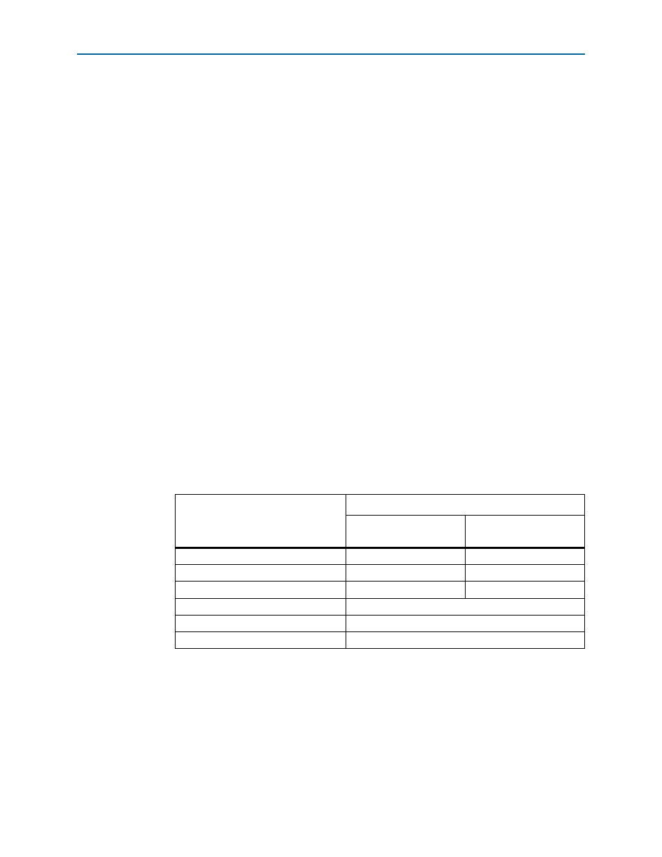
Table 3–6
shows the transmit and receive nominal latencies of the design example.
Table 3–6. Transmit and Receive Latencies of the 10GbE Design Example
Configuration
Latency (Clock Cycles)
(1) (2)
Transmit
(with respect to TX clock)
Receive
(with respect to RX clock)
MAC and Ethernet loopback
10
13
Dual Core FIFO
6
6
Single Core FIFO
10
10
Soft XAUI PHY
Hard XAUI PHY
Soft 10GBASE-R PHY
Notes to
Table 3–6
:
(1) The clocks in all domains are running at the same frequency.
(2) The latency values are based on the assumption that there is no backpressure on the Avalon-ST TX and RX
interface.
(3) Total latency for both transmit and receive in this design example targeting the Stratix IV device family.